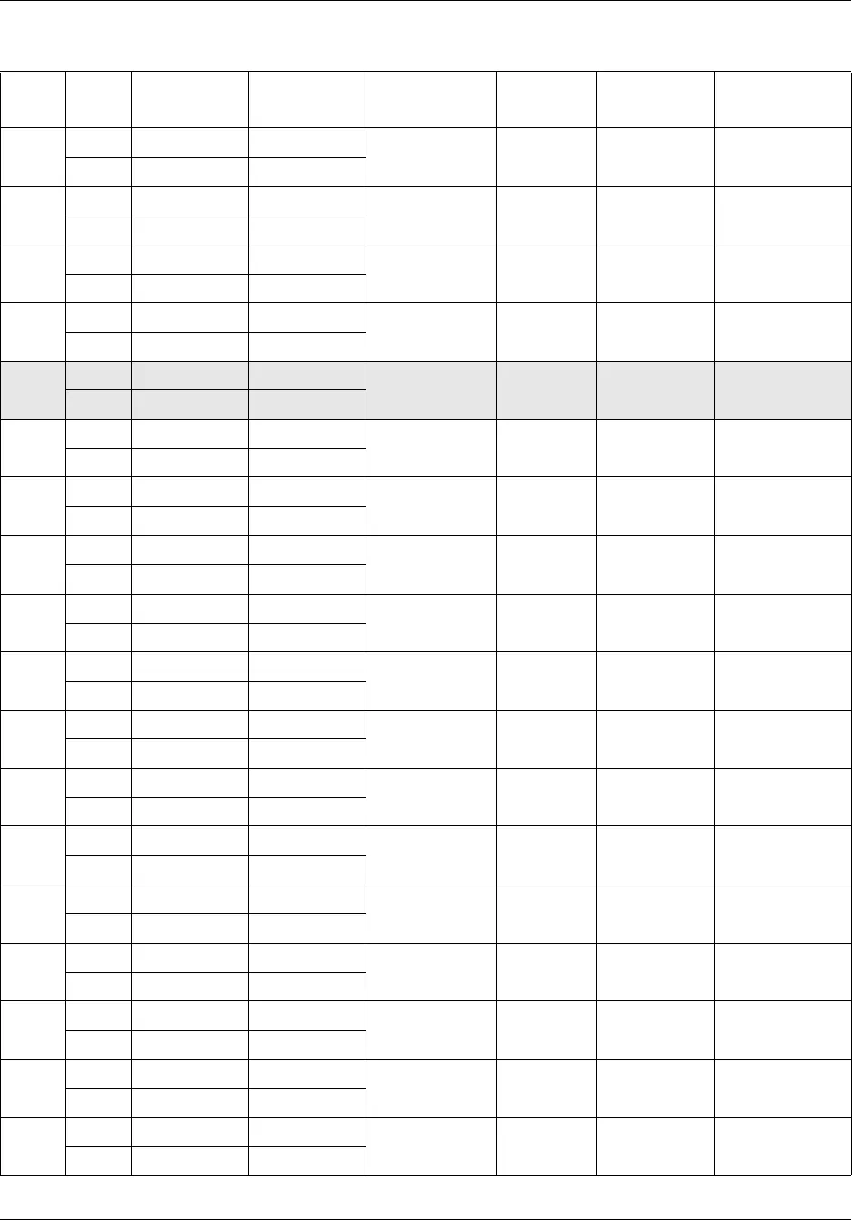
210 Appendix A RJ-21 telephony connector wiring chart
NN40170-305
5
30 Tip White-Slate
Analog
telephone
413 233 —
5 Ring Slate-White
6
31 Tip Red-Blue
Analog
telephone
414 234 —
6 Ring Blue-Red
7
32 Tip Red-Orange
Analog
telephone
415 235 —
7 Ring Orange-Red
8
33 Tip Red-Green
Analog
telephone
416 236 —
8 Ring Green-Red
9
34 No connection Red-Brown
No connection — — —
9 No connection Brown-Red
10
35 Tip Red-Slate
Auxiliary
Ringer
—— —
10 Ring Slate-Red
11
36 Tip Black-Blue
Page Relay — — —
11 Ring Blue-Black
12
37 Tip Black-Orange
Page Output — — —
12 Ring Orange-Black
13
38 Tip Black-Green
Music Source — — —
13 Ring Green-Black
14
39 Tip Black-Brown
Digital
telephone
412 232 —
14 Ring Brown-Black
15
40 Tip Black-Slate
Digital
telephone
411 231 —
15 Ring Slate-Black
16
41 Tip Yellow-Blue
Digital
telephone
410 230 —
16 Ring Blue-Yellow
17
42 Tip Yellow-Orange
Digital
telephone
409 229 —
17 Ring Orange-Yellow
18
43 Tip Yellow-Green
Digital
telephone
408 228 —
18 Ring Green-Yellow
19
44 Tip Yellow-Brown
Digital
telephone
407 227 —
19 Ring Brown-Yellow
20
45 Tip Yellow-Slate
Digital
telephone
406 226 —
20 Ring Slate-Yellow
21
46 Tip Violet-Blue
Digital
telephone
405 225 —
21 Ring Blue-Violet
22
47 Tip Violet-Orange
Digital
telephone
404 224 —
22 Ring Orange-Violet
Table 33 RJ-21 telephony connector wiring (Sheet 2 of 3)
Device Pin Connection Wire color Type of device Port Default DN
Default line
number


