Part Number 305418-B Rev 00 3
Command Shortcuts
• To recall any command from the history list, press the up arrow (or Control-p) or down arrow (or Control-n).
• Enter the first few letters of any command and press Return. The BCC automatically completes any command
for which it finds a unique match in the current context. Otherwise, the BCC displays choices or an error
message based on your partial entry.
Help Tips
• To see an overview of the Help system, enter help or help help
• To see a list of all system (nonconfiguration) commands, enter help commands or help commands -more
• To see Help for a specific command, enter help
<command>
, for example, help compact or help ip
• To see text definitions for the parameters of any object configurable at your current location in the tree, enter
help
<parameter>
(for example, help bofl) or enter help
<object_name>
(for example, help ip)
• When the BCC displays a list of choices for help on a configuration object, copy and paste the command line
that best describes the path from root to that object in the tree, for example, help box ip (global IP) or for
interface IP, help box ethernet ip or help box serial ppp ip
Interface Conventions
The following table describes the conventions for slot, module, and connector numbering on each router platform.
Platform Syntax
AN/ANH
<interface> <slot> <connector>
•
<interface>
= interface type: ethernet, token-ring, serial, etc.
•
<slot>
= 1 (The AN/ANH is a single-slot device.)
•
<connector>
numbering starts with connector 1.
Example:
ethernet slot 1 connector 3
This is an Ethernet interface configured on AN/ANH connector 3, which exists on an Ethernet adapter module.
(Connectors 1 and 2 are on the base module.)
ARN
<interface> <slot> <connector>
•
<interface>
= interface type: ethernet, token-ring, serial, etc.
•
<slot>
= 1 (The ARN is a single-slot device.)
•
<connector>
numbering depends on the port type (LAN or WAN). LAN connector numbering starts at 1 on
the base module, which contains only LAN ports, and continues in ascending order, starting with the first
LAN port on an ARN expansion module. (The ARN expansion module plugs into the ARN base module.)
WAN connector numbering starts with connector 1 on WAN adapter module 1, continues with connector 2
on WAN adapter module 2, and ascends sequentially with WAN connectors 3 through
n
on the ARN
expansion module.
Example:
ethernet slot 1 connector 2
This interface is configured on LAN connector 2, which exists physically on an Ethernet expansion module.
(Ethernet connector 1 is on the base module.)
Example:
serial slot 1 connector 3
This is a serial (WAN) interface configured on WAN connector 3 on the ARN expansion module.
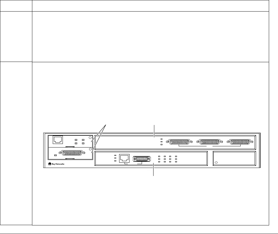
Adapter modules
Expansion module
Base module
COM3 COM4 COM5
COM
U
D
DD
B1
B2
RLSD
Run
Boot
Fail
Pwr
RPS
Fan
Base
Adapter1
Adapter2
Expansion
DCM
PCMCIA
BayStack Advanced Remote Node
RLSD3
RLSD4
RLSD5
1
2
Serial
Serial
ISDN BRI
withNT1
Tx
Rx
Cl
10BaseT
AUI
Ethernet 1


