This Self Study Programme contains
information on data bus networking
(topology) and electrical components in the
Audi A8 ´03.
An understanding of the interaction of the
components and distributed functions forms
the necessary basis for successful
fault-finding.
Wiring
This introduction contains explanatory notes to
clarify the meanings of certain terms, designations
and symbols used in this Self Study Programme.
More detailed information can be found in the
following Self Study Programmes:
– SSP 282 – Audi A8 ´03 Technical Features
– SSP 286 – New Data Bus Systems –
LIN, MOST, Bluetooth
TM
– SSP 288 – Audi A8 ´03 Distributed Functions
– SSP 289 – Adaptive cruise control in the
Audi A8 ´03
– SSP 293 – Audi A8 ´03 Infotainment
Components and symbols
1
Definition of terms
Data bus network (topology)
The topology provides a general outline of the
way in which control units fitted in the vehicle
are interlinked by way of data bus systems.
It thus becomes clear which bus systems are
used by the control units to exchange data.
Distributed functions
This term indicates that several control units
are required to exchange information in order
to implement a function.
Example: Wiper speed 1 function
Function master
With distributed functions, one control unit is
always responsible for the entire sequence of
operations. The function master control unit
gathers all input information. The requests
resulting from this are then transmitted in the
form of a message on the data bus system
and read into the control units concerned for
corresponding actuation of the appropriate
connected components.
Substitute master
In the event of function master failure
affecting major functions, the task of the
function master is assumed by a control unit
provided for this purpose and designed to
maintain the sequence of operations
(possibly with certain restrictions).
SSP287_005
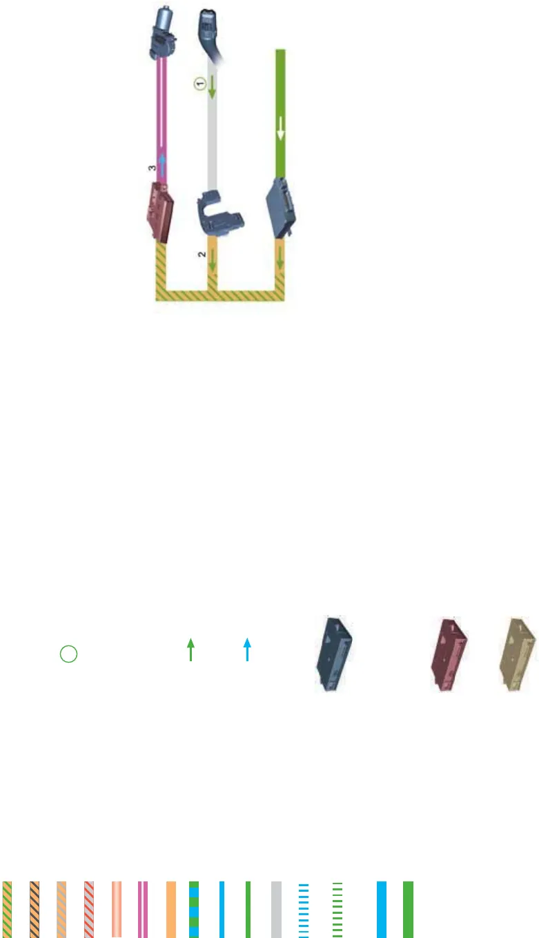
Ignition ON
J518
J527
J519
J400
E22
Prerequisite
Ignition switched on by way of electric
ignition/starter switch or Advanced Key, so
that entry and start authorisation control unit
J518 transmits terminal 15 and 75x
information to convenience CAN.
1 The intermittent wiper switch E22
transmits the information "Wiper speed 1"
to the steering column electronics
control unit J527.
2 The steering column electronics transmits
the information "Wiper speed 1" to the
onboard power supply control unit J519.
3 The onboard power supply control unit
transmits the information "Wiper speed 1"
via the LIN to the wiper motor control unit
J400.
The wiper motor control unit actuates
the integrated motor.
Convenience CAN
Drive system CAN
Adaptive cruise control CAN
Dash panel insert CAN
MOST bus
LIN bus
Diagnosis CAN
Bidirectional wire
Reception wire
Transmission wire
Discrete wire
Wireless transmission
– transmission signal
Wireless transmission
– reception signal
Follow-up function
Prerequisite
A number is used to
designate the information
sequence described in the
corresponding text.
The green circle symbolises
the start of an information
sequence.
The green arrow indicates
input information.
The blue arrow indicates
output information.
The layout of the individual
components such as control
units, switches or control
elements as illustrated
corresponds to the actual
arrangement in the vehicle.
Component designations are
explained on the basis of their
identifiers in the relevant text.
Components marked in red
indicate the function master
within a sequence of
operations.
Components marked in
yellow indicate the substitute
master.


