K2 Internal Mic Adaptor (IMA) User’s Guide – 23 July 2013
13
External Bias
–
Circuit Description
Caution! You Must Know Your Microphones!
Bias Will Damage An “Unprotected” Dynamic Element!
If your mic has
a dynamic element, you normally won’t
apply external bias!
an electret element, you may need to
Biasing
◥
entails inserting a resistor between AF
(Bypass)
and +5V
(Bias)
. The Elecraft
®
KSB2 manual
◥
only calls
for three bias resistances (820 Ω, 5.6 kΩ, and 10 kΩ), but four more are possible (2.2 kΩ, 3.6 kΩ, 4.4 kΩ, and 9.2 kΩ).
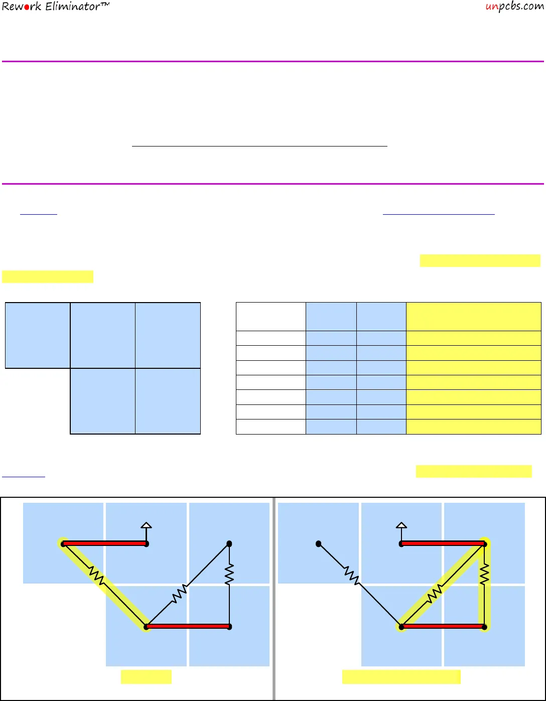
The diagram (below left) shows the arrangement of the external bias pins, while the table (below right) describes how to
jumper these five pins to insert the seven possible bias resistance values. The table also includes a summary description of
the resulting circuit.
R3
Bias
+5V
R1
R2
Bypass
AF
+5V
AF
Circuit Description
2.2
3.6
4.4
9.2
This next table (continued on the following page) graphically presents the information listed above. It overlays the
schematic on the jumper block, creating pictures that show the configuration of the jumpers and the resulting circuit path.
820
Just R3
R1 + R2 in Parallel
2.2
Bypass
Bias
+5V
R2
3.6K
R1
5.6K
To AF
R3
820
Bypass
Bias
+5V
R2
3.6K
R1
5.6K
R3
820
To AF


