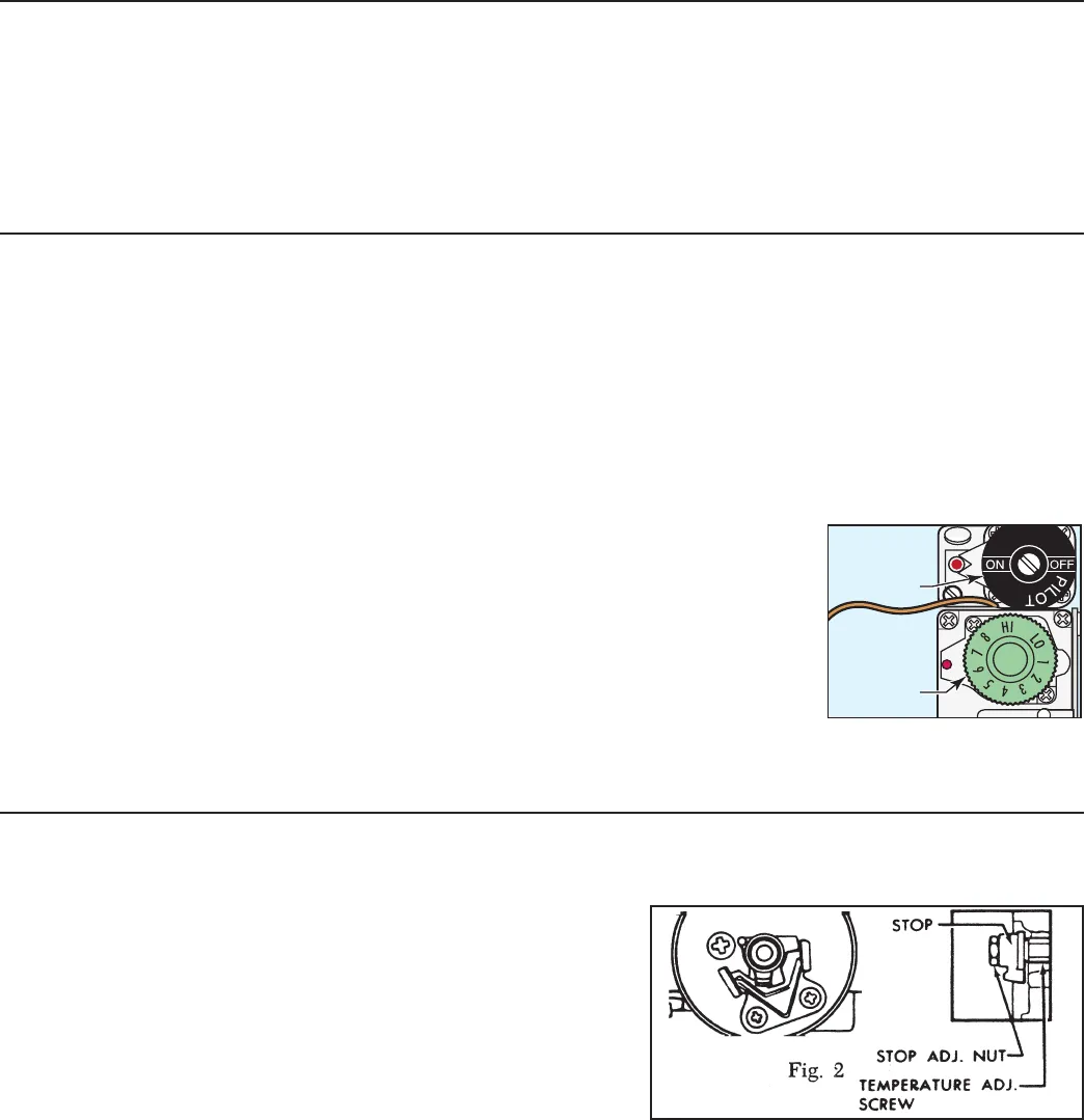
Fig 1. Dial on the gas thermostat
set at 6½.
PILOT
DIAL
THERMOSTAT
DIAL
GAS URN INSTALLATION
The urn must be away from wall no less than 6” and must have plenty of cross ventilation.
The water supply connection is the same in all RU models. All that is needed is 1/4” copper tubing with a 1/4” are nut and some sort of water lter in the line before water enters
the unit. Once the water connection is complete, open the water line, then plug in the power cord into an 115V outlet. To facilitate the lling of the water jacket, you can open the
emergency rell faucet (red knob) behind the unit, to increase the speed of lling the urn. Water must be above the base of the center gauge glass before turning on the heat.
GAS CONNECTION
All RU automatic urns are supplied with a 3/8” pressure connector at the end of the gas valve. This valve is connected to the thermostat. Use 3/8” O.D. stainless steel ex tubing to
make the connection from the urn to the gas valve in your facility. When the connections are complete, turn the gas on. Check the line for leaks.
PROCEDURE FOR LIGHTING OR RELIGHTING PILOT
1. Remove the pilot control cover on the right side of the thermostat cover (held in place by four screws).
2. Turn the pilot dial to the OFF position and thermostat dial to the lowest temperature position.
3. Allow sufcient time for any gas that may still be in the burner compartment to dissipate.
4. Push in the pilot dial (the dial has a slight inward travel) and rotate it to the PILOT position. On older units, there is a separate red
SET button that must be pushed in to allow the dial to turn.
5. Continue pressing in the dial while lighting the pilot burner. The pilot is located inside the burner compartment, between the main
burners.
6. Once lit, allow the ame to burn for approximately 30 seconds before releasing pilot dial. If the pilot ame does not remain lit,
repeat the operation, allowing for a longer period before releasing the pilot dial.
7. Turn the pilot dial to the ON position. Turn the thermostat dial to the desired position. The main burner will then ignite.
MAIN BURNER ADJUSTMENT
To adjust the main burner ame, turn the thermostat dial to 6½ for 195ºF or 7 for 200ºF; see gure 1. For older units (made before se-
rial number 12327781), turn the screw under the gas cock handle in either direction to regulate the ow of gas to the main burner.
TO RE-CALIBRATE THE THERMOSTAT
The Unitrol thermostat is built to the most exacting standards and is a precision instrument which should never need re-calibration. However because of tampering, misuse or
other reason, if the thermostat is found to be more than 10º from normal, a re-calibration may be performed by a qualied service technician. The following are the steps for this
procedure:
1. Turn the thermostat to OFF to allow the unit to cool down.
2. When the water temperature is room temperature, turn the thermostat dial until the main burner
ignites.
3. Slowly, turn the thermostat dial counterclockwise until the ame on the burner goes out.
4. Place a thermometer into the water jacket to determine the temperature of the water.
5. Pull off the thermostat dial and lift off the outside cover.
6. Turn the temperature stop to correspond to the actual water temperature. Mark the location of the stop
for reference.
7. Turn the stop slowly until the control snaps off. Holding the stop to prevent rotation, carefully loosen
the stop adjustment nut (see gure 2).
8. Taking care not to move the temperature adjusting screw, turn the stop until it lines up with the tick mark (see step 6).
9. Hold the stop in place and tighten the stop adjustment nut.
10. Recheck the OFF temperature.
11. Replace the outside cover and thermostat dial.
THERMOCOUPLE CONNECTION
Poor contact between the thermocouple lead and the magnet assembly may cause the valve to be inoperative even when the pilot is in proper adjustment and position. If this is the
problem, clean and tighten the contact points. Remove the thermocouple and carefully clean the parts that make contact with the magnet assembly.
PROCEDURE FOR ADJUSTING PILOT
1. Remove pilot adjustment cap. Adjust pilot key, allowing ame to completely envelop the end ( ⅛”) of the thermocouple.
2. Adjust pilot burner air shutter (if provided) to obtain a soft blue ame.
ELECTRIC THERMOSTAT ADJUSTMENT
On electric urns, thermostats are set at the factory to cut off at 200ºF. We do not recommend changing this. If necessary, adjustment is as follows:
1. Rotate the thermostat knob to the right to the BOIL position. Remove the knob by pulling off from the stem.
2. Locate the tiny adjustment screw, inside the stem (see gure 1). Using a small screwdriver, adjust the temperature up or down:
a. By turning the screw ¼ turn to the left will increase the temperature about 20°F.
b. Turning ¼ to the right will decrease the temperature by 20°F.
c. To set the thermostat precisely at 200°F, insert a thermometer probe into the water jacket through the steam hole (just under the sprayhead). Turn the screw ½ turn to the left.
When the thermometer reaches 200°F, slowly turn the adjustment screw to the right until the pilot light turns off.
2


