Shure UC2 Hand-Held UHF Transmitter
2
Characteristics
25C1044 (TK)
Circuit Description
CONTROL
PLL CONTROL
MCU
EEPROM
(MEM)
PWR. OFF DETECT
+5V
REG.
GROUP CHANNEL
SYNTH.
RF POWER
RF MUTE RF MUTE
VCO
FROM
BATT.
UNREG. PWR.
+5v
AUDIO IN
PWR.
HOLD
CIRCUIT
ON / OFF
SWITCH
FET
BYPASS
TONE KEY
CIRCUIT
Σ
TONE CONTROL
TONE KEY
CALL ID
BATTERY
MGMT.
& FUEL
GAUGE
AUDIO
OUT
LIMITER
CONTROL OUTPUT
LIMITER
CONTROL INPUT
MIC
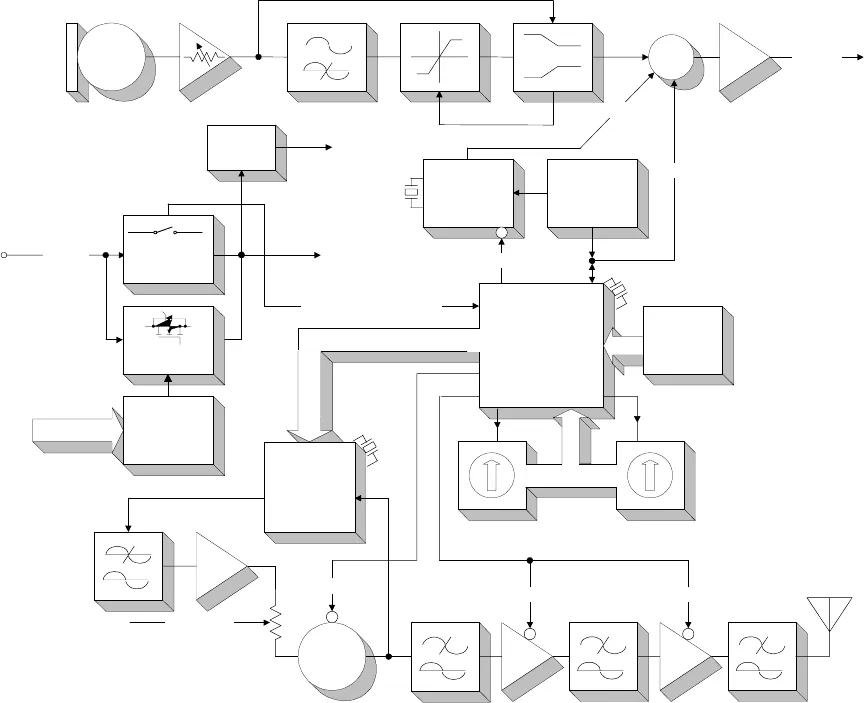
Figure 2. UC2 Hand-Held Transmitter Circuit Block Diagram
32.768 kHz
4 MHz
4 MHz
MB15A02
MC68HC705
Audio Section
FCC-Approved
Audio enters L200, an inductor used as an rf choke. The signal is
ac coupled through capacitor C200 into a user adjustable gain stage.
Resistors R202 and R203 set up a half-supply bias, and R204 sets the
input impedance for the stage.
The back-to-back diodes, D201, are used to keep the op-amp from
snapping to the rail and reverse phasing when the maximum input volt-
age range is exceeded.
The 30 dB adjustable gain stage is built around U200A. The user
externally controls the gain of this stage. C206, C207, and C208 protect


