Net Weight:
135 lbs. (61.4 kg)
FEATURES
• Two 1505-8 KADT Black Widow
®
woofers
• 22XT
™
compression driver
• Sound Guard
™
high frequency
protection circuit
• Trapezoidal enclosure design
• Built-in pocket casters for easy
movement
DESCRIPTION
The redesign of the ever popular SP
™
4
has resulted in the SP
™
4G loudspeaker
system. It is a pseudo three-way speaker
system comprised of a 15" Scorpion
®
Plus woofer with a Kevlar
®
impregnated
cone and a 22XT
™
compression driver
coupled to a CH
®
941 constant directivity
horn.
This unit can be driven in full-range or
bi-amp mode simply by plugging into
the desired jack on the input plate. The
SP
™
4G has a trapezoidal shaped box,
rather than a rectangular shaped box,
that allows arrays to be constructed
much more easily. This shape also
greatly reduces the build-up of standing
waves on the inside of the enclosure.
This ensures a minimum of mid-bass
and mid-range coloration of the
reproduced sound due to the cabinet.
The SP
™
4G is constructed of 3/4"
plywood and is covered with Peavey’s
durable black carpet. Polymer corners
are also a part of the unit to provide
added protection to the enclosure. A
powder-coated, expanded metal grille
covers the lower part of the front of the
enclosure to protect the low frequency
driver from unforeseen accidents.
Sound Guard
™
, Peavey’s proprietary
circuit for high frequency driver
protection, has been included as an
integral part of the crossover for the
SP
™
4G. The input signal is routed
through the Sound Guard
™
circuit in
both full-range and bi-amp modes of
operation. When the high frequency
drive level to the SP
™
4G exceeds a
predetermined threshold the Sound
Guard
™
circuit in engaged. This subtly
decreases the signal level going to the
22XT
™
so that it will not be damaged
due to long-term overpowering. Short
duration transients will not be
attenuated by Sound Guard
™
and have
the possibility to damage the 22XT
™
.
The Sound Guard
™
circuit is a dynamic
circuit that will attenuate the signal
more in relation to how large the signal
is, very similar to a compressor. This is
accomplished through the use of a
specially selected, dynamically resistive
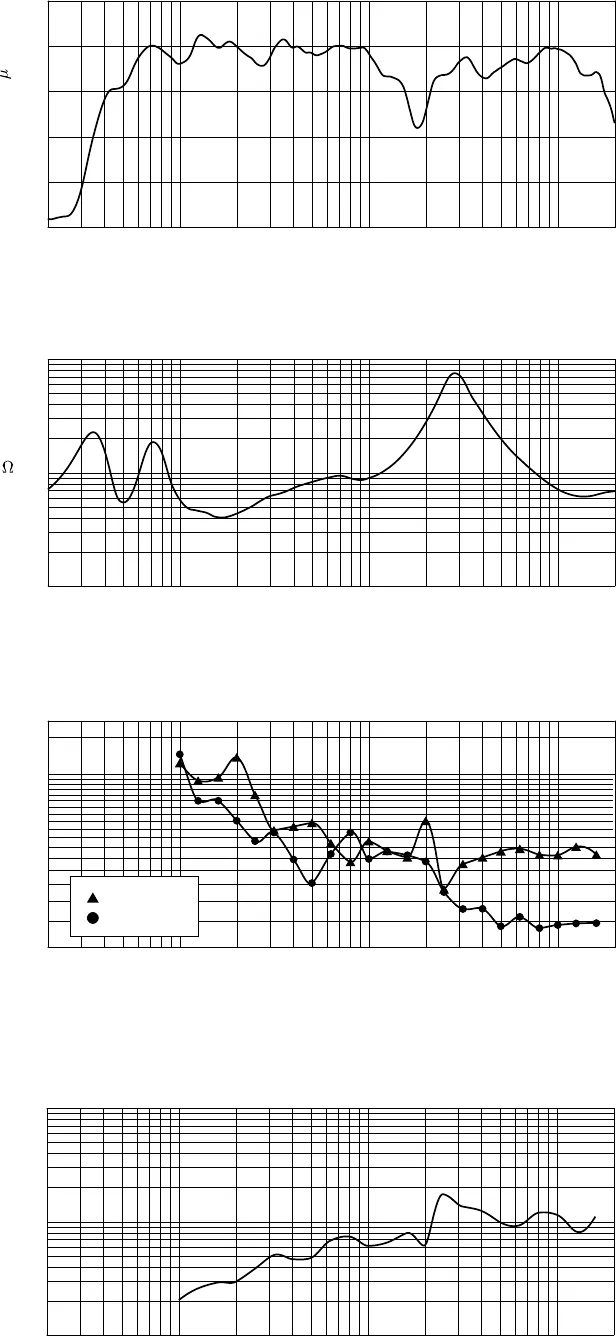
20 50 100 200 500 1k 2k 5k 10k 20k
Frequency (Hz)
30
40
60
80
100
140
180
300
360
Beamw
t
Degrees
Beamwidth
Vertical
Horizontal
Figure 3
20 50 100 200 500 1k 2k 5k 10k 20k
Frequency (Hz)
60
70
80
90
100
110
dB SPL (re 20 Pa)
Amplitude Response (1W 1m On-Axis)
Figure 1
20 50 100 200 500 1k 2k 5k 10k 20k
Frequency (Hz)
1
10
100
Q & Directivity Index
Q
Figure 4
20
10
Di
0
20 50 100 200 500 1k 2k 5k 10k 20k
Frequency (Hz)
1
2
3
5
10
20
30
50
100
Impedance
Z
(
)
Figure 2


