13A-18
MPI – TROUBLESHOOTING
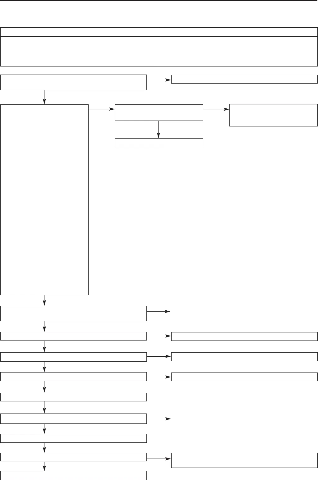
Measure the output wave from
the crank angle sensor and the
cam position sensor (using an
oscilloscope).
• Engine: idling
<Crank angle sensor>
• Measure the output wave at
the crank angle sensor
connector B-122
• Connect test harness
(MB998478), to the connector,
and take measurements at the
pick-up harness component
•Voltage across earth at 2
<Exhaust cam position sensor>
• Measure the output wave at
the exhaust cam position
sensor connector B-115
• Connect test harness
(MB991709), to the connector
and take measurements at the
pick-up harness component
•Voltage across earth at 2
OK: The output wave timing
from both sensors is as
shown on P13A-25
(Main points for
oscilloscope testing).
Check that the problem has been
solved
Temporary malfunction (Ref
Section 00: Dealing with
temporary malfunctions)
Replace the engine ECU
NO
OK
NG
OK
NG
NG
NG
Repair
Miss-timed ignition Probable causes of the malfunction
Probable causes of the malfunction are noted in the right
hand column.
• Malfunction of the crank angle sensor
• Malfunction of the exhaust cam position sensor
• Malfunction of the timing belt
• Malfunction of the engine ECU
Inspection procedure 15
Refer to the diagnosis code classification table (P13A-6)
MUT-II/III Diagnosis code
• Is the diagnosis code displayed?
YES
Repair
Replace the crank angle sensor pane
Match up the timing marks on the timing belt
Replace the exhaust cam position sensing cylinder
Temporary malfunction (Ref Section 00: Dealing with
temporary malfunctions)
Check the exhaust cam position sensing cylinder
Check the fitting of the crank angle sensor and the
exhaust cam position sensor
Check the timing marks on the timing belt
Check the crank angle sensor pane
Replace the crank angle sensor
Check that the problem has been solved
Replace the exhaust cam position sensor
Check that the problem has been solved
Replace the engine ECU
OK
OK
OK
NG
OK
NG
NG
NG
OK
OK