MAINTENANCE SCHEDULE & CHECKLISTS
4012/16 Diesel, February 1997 5
8
EVERY 250 HOURS OR EVERY 6 MONTHS
E.g. to adjust valves and bridge pieces on
No. A1 cylinder set No. A6 cylinder valves
rocking for the 4012 engine and No. A8 for
the 4016 engine.
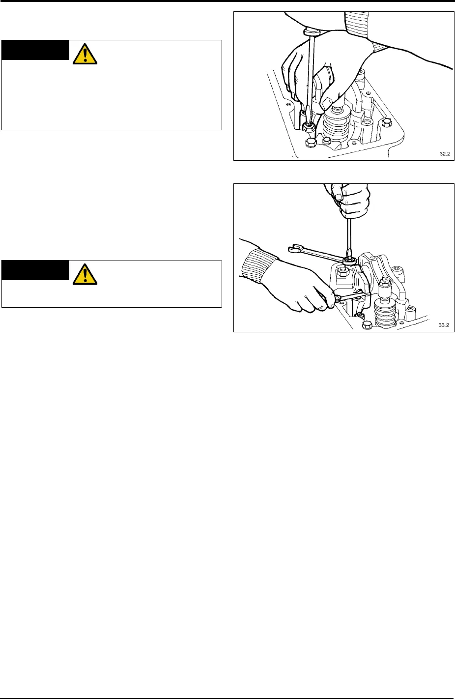
RESETTING THE VALVE CLEARANCES
WITH ENGINE COLD
With both bridge pieces equalised, check
and adjust the valve clearance using a 0.4
mm (0.016") feeler gauge for both the
exhaust and inlet valve set between each
rocker and bridge piece Fig. 53. If required
screw the adjuster until the rocker is bearing
lightly on the feeler gauge. Tighten the lock
nut without moving the adjuster. (See
Torque Settings page 16). The feeler
g
auge should be a slide fit between the
rocker and bridge piece, thereby giving the
correct clearance. Refit the rocker cover
with a new gasket.
For further instructions on maintenance
please refer to the Maintenance Section of
t
he Workshop Manual
.
L
INKAGE FROM THE GOVERNOR TO
THE CONTROL SHAFTS
Check the freedom of operation of these
important linkages, which are vital to the
proper running of the engine.
WARNING
FAILURE TO
EQUALISE A BRIDGE
PIECE MAY RESULT IN ENGINE
DAMAGE. ALWAYS CHECK THAT THE
PARTS FIT TOGETHER AND MOVE
FREELY, BEFORE ASSEMBLY.
WARNING
DISCONNECT THE
BATTERIES AND ALL
OTHER MEANS OF STARTING ENGINE.
Fig. 52
Fig. 53