t
Part
No.
Description
No.
Req'd.
Part
No.
Description
No.
Req'd.
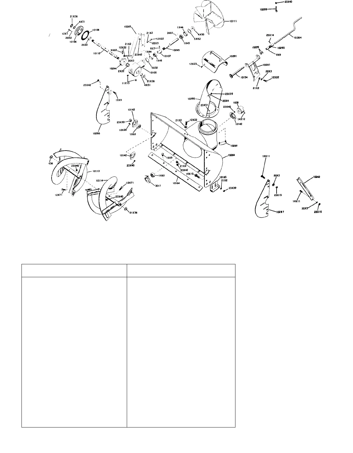
1038
Jaw Clutch
1
4X50
Seal
1
3017
Bearing Flange
1
4X51
Seal
2
10105
Gear Case
1
5X32 Snap Ring
1
10106
Gear Case Flange
1
5XK2
Snap Ring
1
10107 Bearing Spacer
1
9X7
RoU Pin 1/4 X 1-1/4
3
10108
Gasket 1 9X9
Roll Pin 1/8 X 1 1
10110
Fr(mt Gear Shaft
1
9X22
RoU Pin 5/18 X 1-3/8
1
10111
Fan
1
11X13
Pipe Plug 3/8 Sq. Hd. 2
10113 R. H. Rake
1 12X1 Cap Screw H. H. 1/4-20 x 3/4
5
10114 U H. Rake
1
12X22 Cap Screw H. H. 5/16-18 x 3/4 4
10142 Bearing Flange
5
12X23
Cap Screw H. H. 3/8-16 x 3/4
2
10154 Ccmtrol Sprocket
1
12X28 Cap Screw H. H. 1/4-20 x 1/2 6
10164
Scraper Blade 1
12X71 Shear Bolt 2
10165
Runner 2
14X12 Socket Set Screw 5/16-18 x 3/8 2
10229
Wave Washer 1 or 2
19X9
Carriage Bolt 5/16-18 x 1/2
11
10242
Sllcer Bar
1
19X10
Carriage Bolt 3/8-16 x 3/4
4
10244 Helicon Gear 1
19X11 Carriage Bolt 5/16-16 x 3/4
3
10245
Helicon Pinion Shalt
1
20X2 Lockwasher 1/4
5
10264 Blower Housing
1
20X3 Lockwasher 5/16
7
10265 Front Gear Case Support 1
20X4 Lockwasher 3/8 4
10269 Chute Clamp 3
21X2
Wrought Washer 5/16
15
10281 Chute Control Support
1
21X36
Washer .880 ID x 1.375 x 1/16 4
10284
Chute Cmitrol Crank
1
23X15
Hex Nut 5/16-18
3
10286 R. H. Rotor Shield 1
23X30 Hex Locknut 3/4-16 2
10287 L. H. Rotor Shield 1
23X39 Hex Locknut 3/8-16
6
10289
Rod Hanger
1
23X40
Hex Locknut 1/4-20
12
10290
Universal Joint
1
23X42 Hex Locknut 5/16-18
13
10291
Deflector Chute
1 23X51
Keps Nut #10-24
6
10292 Discharge Chute
1
24X1
WoodruH Key #11
1
1X44 Bearing Cup
2 25X14
Cotter Pin 1/8 X 1-1/4
1
1X45
Bearing Cone
2
LABELS NOT ILLUSTRATED
1X63 Ball Bearing
3
40X12
Sno-Thro Label 1
2X22
Flange Bushing
2
40X14 Cauti(xi Label
1
OPERATING INSTRUCTIONS
1. ATTACHING
a. Sno-Thro Attachment.
(1) Hook the notches in the lower portlcm of the
Sno-Thro Attachment frame over the rod passing
through the forward section of the tractor frame.
(2) Tip the two sections tc^ether, being sure
the jaw clutch on the Sno-Thro Attachment and trac
tor are lined up.
(3) Insert and tighten the two 3/8-lnch cap
screws through the top of the tractor frame and into
the Sno-Thro Attachment.
b. Chute Control Rod.
(1) Insert the rod hanger through the hole in
the upper handle bar and secure with the 1/4-inch
locknut.
(2) Fasten the chute control support to the
tractor with the hardware provided. Poslticm the
support so that the gear meshes properly with the
holes in the chute. Fasten securely.
(3) Slide the chute control rod through the rod
hanger and into the end of the universal joint. Se
cure the rod to the universal joint with a cotter pin.
Page 33


