2 | I n s t r u c t i o n S h e e t K G - 2 0 0 2
3. Technical Data
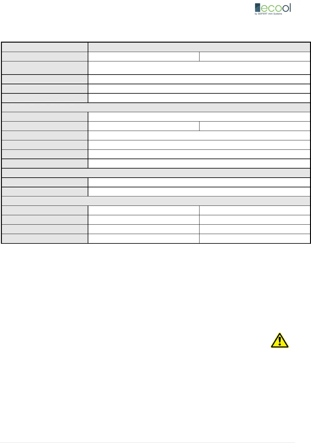
KG-2002
Part- No 20020240 20020480
Housing material/Surface finish
Mild steel, powder coated RAL 7035
Optional: stainless steel, Part-no. 20xx … 2
Housing dimensions 260 x 203.2 x 220 mm
Weight 6.8 kg
Operational temp. range +10°C ... +55°C
Cooling performance according to DIN 3168 L35 L35
Max. Cooling capacity @ L35L35 480 W
Max Power consumption L35L35 295 W 380 W
Compressor Speed controlled rotary compressor
Refrigerant R134a
Refrigerant load 82g
Max. working Pressure PS 40 / PO 37bar
Maximum air volume flow
Ambient air circuit 280 m
3
/h
Cabinet air circuit 190 m
3
/h
Electrical data
Nominal Voltage 24 V DC 48 V DC
Operating Voltage Range 20 ... 30 V DC 43 ... 60 V DC
Rated current (max) 14.5 A 10.2 A
Power Consumption at max. Conditions 350 W 490 W
The company reserves the right to make technical changes.
4. Ambient Fans
The ambient fans could be mounted either on the left or right hand side of the unit, depending on the preferred ambient inlet location.
To change the location of the ambient fans:
- Disassemble the main cover, disconnect connectors, and remove blowers from rubber mounting.
- Remove blanking plates, and mount blowers on the other side of the unit.
- Place blanking plates on the other side of the unit.
- Connect connectors, and close main cover.
When changing the location of the ambient blowers always make sure the following:
-Fans are properly assembled to the rubber mounts
-Both fans are blowing in the same direction
-Blanking plates are used in the cut-outs not in use.
For optimum performance it is recommended that the fans are assembled in such a way that the fans are blowing towards the condenser and
not sucking out of the condenser.


