Connections
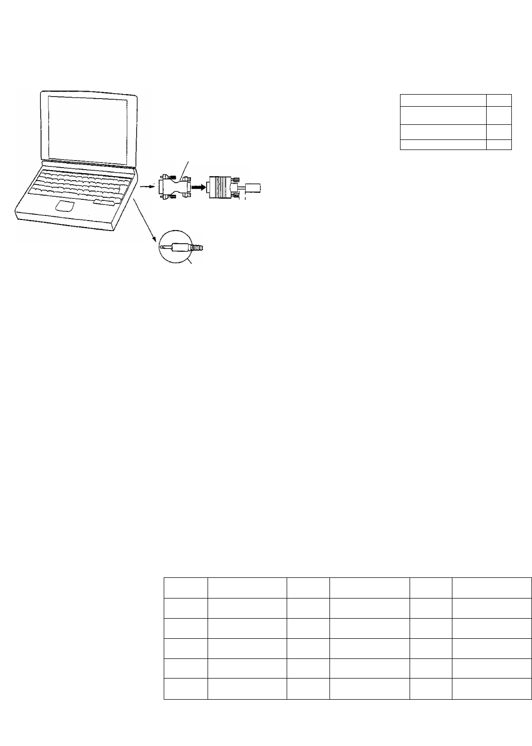
How to connect the PC Input Terminals
COMPUTER
The Wide Plasma Display
rear terminals
Conversion adaptor (if necessary)
RGB
TUNER IN
REMOTE
/ OOOOOQOOOOOO ’I fiN
(pooooooooooooj 12J
©
©
©
Pd‘IN “
SERIAL
^
__
RGB cable
less than 20 cm
D-sub 15p
less than 20 cm
AUDIO
Connect a cable which matches
the audio output terminai on the
computer.
3mm Stereo Plug
Note;
(1) Computer signais which can be input are those with a horizontai scanning frequency of 15.6 to 50 kHz and a vertical
scanning frequency of 50 to 75 Hz. (However, signais cannot be displayed if they have a horizontal scanning
frequency of less than 30 kHz and a vertical scanning frequency of more than 65 Hz, or a horizontal scanning
frequency of more than 40 kHz and a vertical scanning frequency of less than 55 Hz.)
(2) The display resolution is a maximum 640 x 480 dots when the aspect mode is set to “4:3”, and 852 x 480 dots when
the aspect mode is set to “16:9”. If the display resolution exceeds these maximums, it may not be possible to show
fine detail with sufficient clarity.
(3) The PC input terminals are DDC1/2B-compatible. If the computer being connected is not DDC1/2B-compatible, you
will need to make setting changes to the computer at the time of connection.
(4) Some PC models cannot be connected to the set.
(5) An adapter is required to use the RGB cable (D-sub 15P) to connect a PC-98 series computer (which has a D-sub
15P terminai) or a Macintosh computer to the set.
(6) There is no need to use an adapter for computers with DOSN compatible D-sub 15P terminal.
(7) The computer shown in the illustration is for example purposes only.
(8) Additional equipment and cables shown are not supplied with this set.
(9) The picture wiii become dark if a PC signal with a vertical scanning frequency of over 62 Hz is input. To obtain the
optimum picture quality with the Wide Piasma Dispiay, a vertical scanning frequency of 60 Hz is recommended.
(10) Do not set the horizontal and vertical scanning frequencies for PC signais which are above or below the specified
frequency range.
Signal Pin-out for D-sub 15P Connector
® ® ® ® ®
® © CD (D ®
© © © © ©
Pin Layout for PC Input
Terminal
Pin No.
Signal Name
Pin No.
Signal Name Pin No. Signal Name
©
R
©
GND (Ground)
©
GND (Ground)
©
G
©
GND (Ground) SDA
©
B
©
GND (Ground)
©
HD/SYNC
0
GND (Ground)
©
NC (not connected)
©
VD
©
GND (Ground)
©
GND (Ground)
©
SCL
14


