7
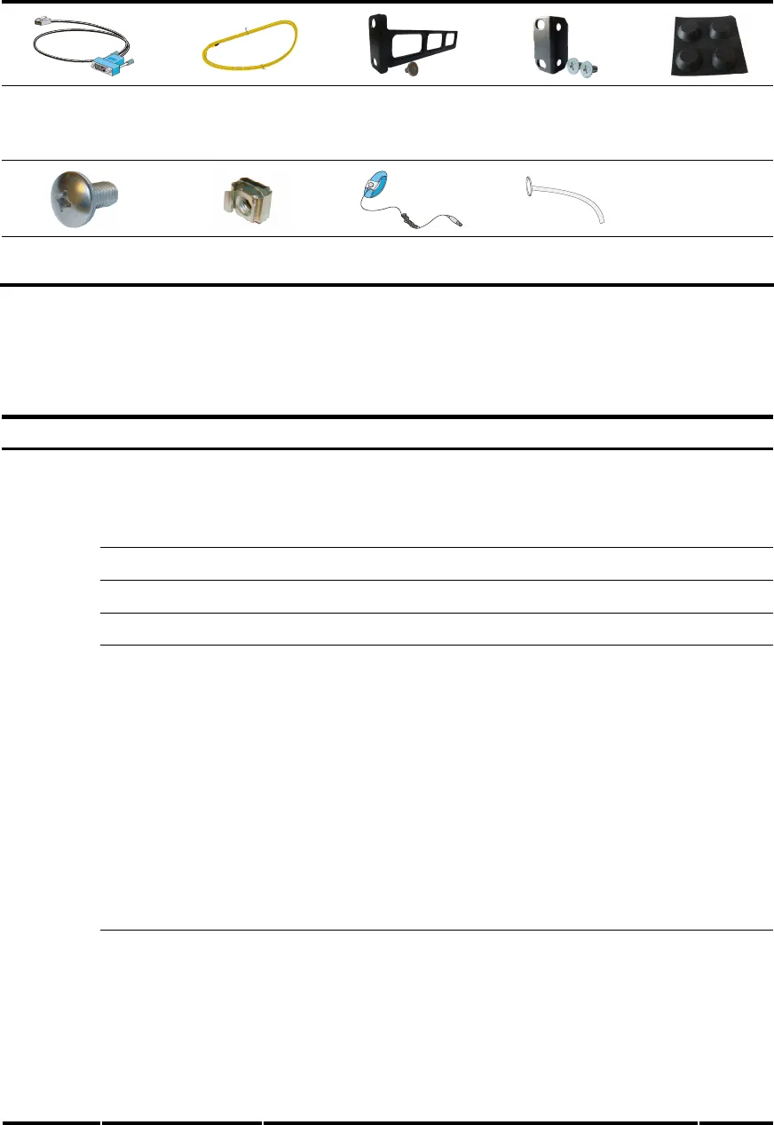
Installation accessories
Console cable Grounding cable
Rear mounting
bracket and
load-bearing screw
Front mounting
bracket and M4
screws
Rubber pads
M6 screws Cage nuts
ESD-preventive
wrist strap
Cable tie
Checklist before installation
Table 6 Checklist before installation
Item Requirements Result
Ventilation
• There is a minimum clearance of 10 cm (3.9 in) around the
inlet and exhaust vents for heat dissipation of the router
chassis.
• A ventilation system is available at the installation site.
Temperature 0°C to 45°C (32°F to 113°F)
Relative humidity 10% to 95% (noncondensing)
Cleanness Dust concentration 3 × 10
4
particles/m
3
ESD prevention
• The equipment and floor are well grounded.
• The equipment room is dust-proof.
• The humidity and temperature are at a proper level,
respectively.
• Wear an ESD-preventive wrist strap and uniform when
touching a circuit board.
• Place the removed memory module, CF card, or
HIM/MIM on an antistatic workbench, with the face
upward, or put it into an antistatic bag.
• Touch only the edges, instead of electronic components
when observing or moving a removed memory module,
CF card, or HIM/MIM.
Installation
site
EMI prevention
• Take effective measures to protect the power system from
the power grid system.
• Separate the protection ground of the router from the
grounding device or lightning protection grounding
device as far as possible.
• Keep the router far away from radio stations, radar and
high-frequency devices working in high current.
• Use electromagnetic shielding when necessary.


