Installation Instructions MFM, PFM, MFQ, PFQ
9
Tilting Display
The display can be tilted from 15
o
to 45
o
.
1. Turn knob counterclockwise on back of head assembly to
loosen the tilt. (See Figure 9)
Figure 9
2. Tilt display as desired, to a maximum of 45
o
either forward
or backward.
3. Turn knob clockwise to tighten display on head assembly.
(See Figure 9)
CAUTION:
Tighten knob on back of head assembly to
prevent damage when moving the cart and display.
4. If leaving the display in a midway position (30
o
tilt), it is
recommended that a bolt (not provided) be placed through
the head assembly (see Figure 9) to lock the display into the
midway position.
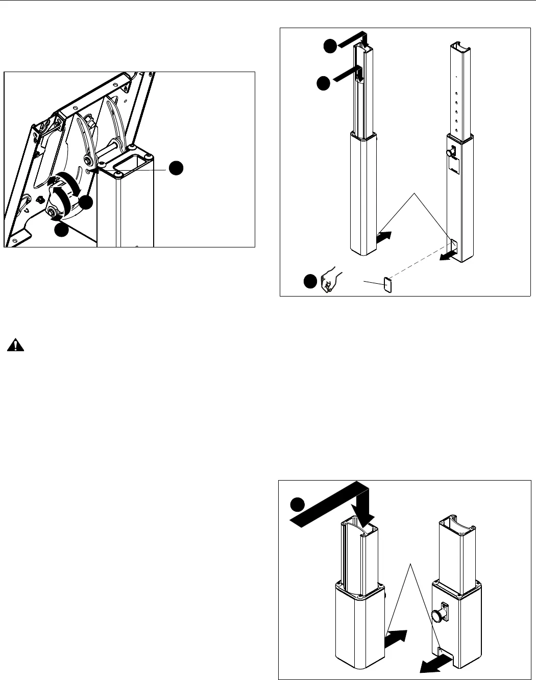
Cable Management
MFM/PFM Models Only
1. Signal cables and display power cord can be run through
the top and down through the post to exit out the back. (See
Figure 10)
2. Any accessory power cords can be run through the front
and down through the post to exit out the back. (See
Figure 10)
Figure 10
3. Install the snap-on covers to any opening that is not being
used. (See Figure 10)
4. To remove the snap-on covers, grip the sides of the cover in
the middle and pull off. They can also be removed by
inserting a flat-blade screwdriver into the bottom slot and
rotating the screwdriver.
5. Proceed to Cart Use and Maintenance.
MFQ/PFQ Models Only
1. Signal cables and display/accessory power cords can be
run through the top and down through the post to exit out the
back. (See Figure 11)
Figure 11
lock display
lock display
1
3
4
(MFM Shown)
Place optional bolt
(not provided) here
to lock in a midway
position (30
o
tilt)
(Rear
view of
center post)
(Front view
of center post)
Exit for
1
2
(J)
cables
3
(MFM/PFM Shown)
Exit for
cables
(MFQ/PFQ Shown)
(Front view
of center post)
(Rear
view of
center post)
1


