Installation
Chapter 2
23
To access the PROM socket, remove the Mini–PLC–2/15 processor module
from the I/O chassis. If you desire to maintain processor memory contents,
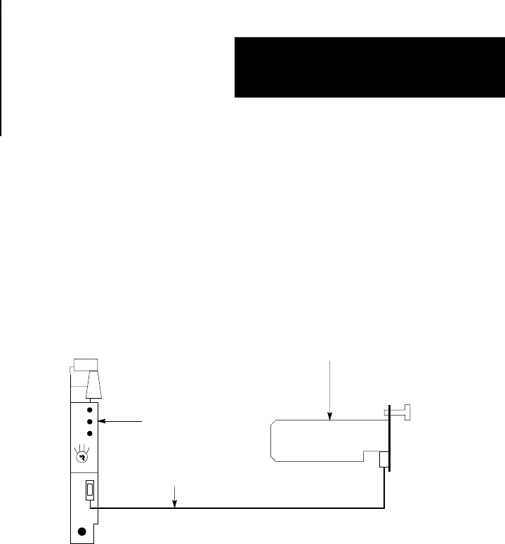
connect an external battery pack (Figure 2.3) to the processor with the
Mini–Processor Transport Cable (cat. no. 1772–CD) prior to removing the
module from the chassis.
Figure 2.3
External Battery Backup
MiniPLC2/15 Processor
(Cat. No. 1772LV)
Battery Pack
(Cat. No. 1771BB)
MiniProcessor
Transport Cable
(Cat. No. 1772CD)
11182
To install the AF1, perform the following steps (Figure 2.2)
1. Turn the mode select switch to PROG.
2. Remove AC power from the I/O chassis power supply.
3. Remove the processor module from the I/O chassis.
4. Check all AF1 pins to ensure they are not bent or dirty.
5. Loosen the screw and lift the PROM door.
6. Push the ON tab in to unlock the socket.
7. Position the AF1 as shown in Figure 2.2 Be sure the notch on your AF1
PROM faces the OFF tab.
8. Line up the AF1 as shown in Figure 2.2 and seat in the socket. Be sure the
pins are aligned as they bend easily.
9. Lock the AF1 in place by pushing the OFF tab in.
10.Close the PROM door and tighten the screw.


