Programming
Chapter 3
39
Figure 3.4
AF1
Addition Function Format After Execution
171615141312111076543210
S
02
Bit No
Data Address
Operand 1
Operand 2
S
Result Address
Result
DERE
E = Enable Bit (1 = Function in Progress)
S = Sign Bit (1= Negative)
D = Done Bit (1 = Function Complete)
ER = Error Bit (1 = Overflow)
11483
Word 201
Word 202
Word 203
Word 204
Word 305
Word 306
(0)
S
(0)
1
467
562
843
593
301
(0) (0) (1) (0)
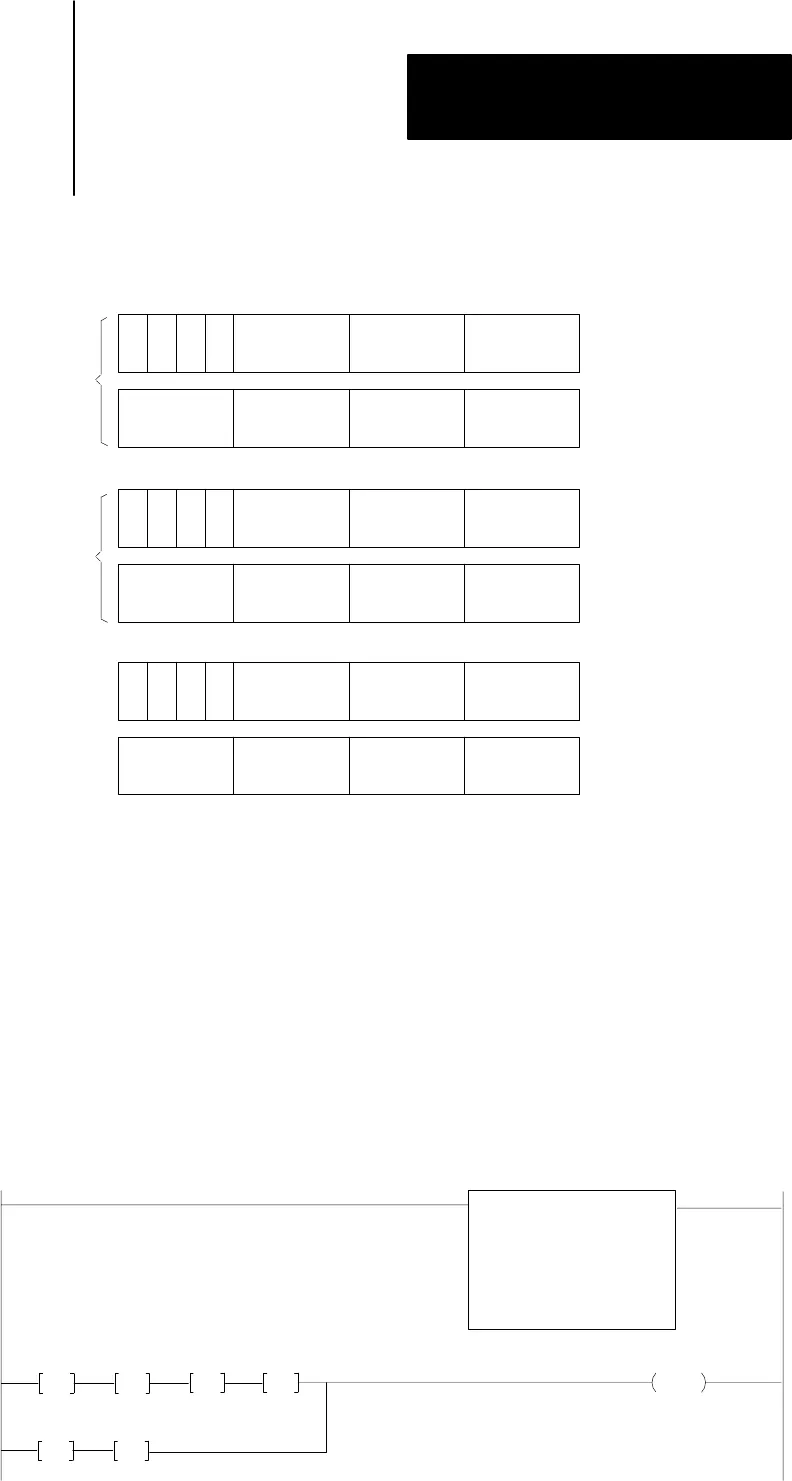
Entry and Display of Input and Result Values
Figure 3.5 shows one method for inserting input values and displaying input
values and results of AF1 addition computations. Although there are several
techniques for accomplishing this, we chose get instructions. The first rung
requests an AF1 addition. The second rung shows the two operands in its top
branch and the resultant sum in its lower branch.
Figure 3.5
AF1
Addition Function Input and Result Display Rungs
Bit
Storage
204
384
G
203
256
G
202
746
G
201
102
G
305
359
G
306
130
G
Execute Aux
Function
Function Number:
Data Addr:
Result Addr:
01
201
305


