2
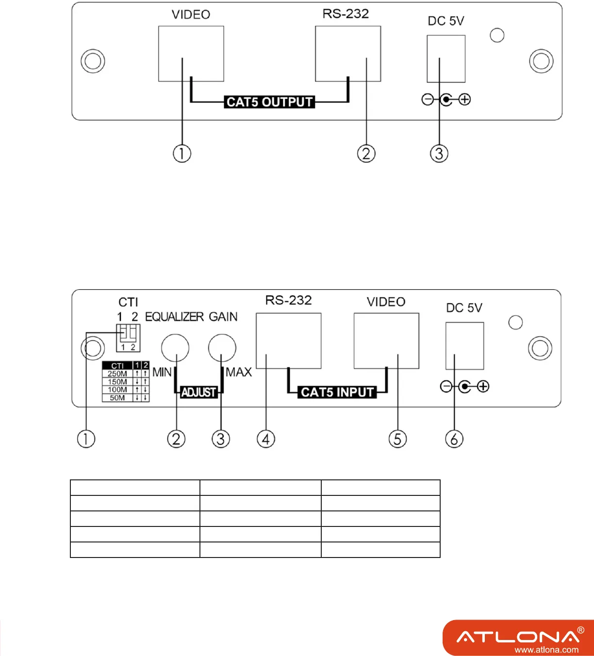
Transmitter’s Rear Panel
1, VIDEO CAT5/6/7 OUTPUT - Connect the VIDEO output to the VIDEO input of receiver with
CAT-5/6/7 cable.
2. RS232 - Insert CAT 5 cable to the receiver’s rear panel RS232 jack.
3. Power - Connect with 5V / 2.6A power adaptor.
Receiver’s Front Panel
1. CTI dip switch – Setting CTI by using the twin jumpers to adjust the optimized setting for
different distance of connection.
CTI 1 2
150 - 250m ↑ ↑
100 - 150m ↓ ↑
50 - 100m ↑ ↓
50 m↓ ↓ ↓
Note: This function is only available on AT-HDS250SR.
3


