USB Receiver
Designer Reference Manual DRM050 — Rev 0
36 USB Receiver MOTOROLA
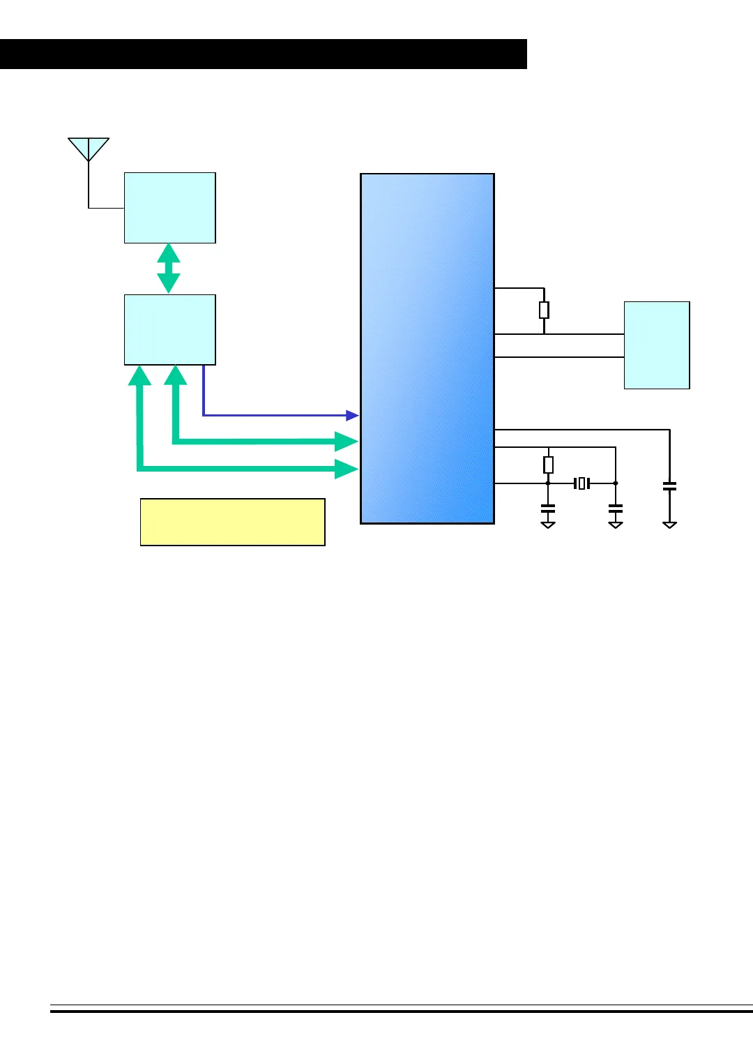
Figure 7-1. USB Receiver Block Diagram
7.2.1 Microcontroller JB16
The functions of the JB16 are to handle the USB transactions, control the
baseband IC to receiving input data, and perform the overall system
control. The processed data is converted into USB report format and
sent to the host.
7.2.2 RF Transmission
The receiving RF signal will be down-converted into IF band for
de-spreading with DSSS scheme and ASK demodulation. The
demodulated data in serial packet format will be converted back to
parallel data and sent to the MCU for USB report generation.
MC68HC908JB16
(28-pin SOIC)
PTE4
PTE3
PTA7-PTA0
PTD5-PTD0
PTC1-PTC0
2.4 GHz RF
Transceiver
Module
LOOP
ANTENNA
Baseband
MAC IC
D100
3.3V Voltage Regulator
PC
Host
DATA BUS
ADDRESS / CTL BUS
RFD_INT
IRQ
OSC1
OSC2
RST
12MHz
30pF
30pF
X1
100nF
10M
D-
D+
1K5
VREG
USB
Frees
cale Semiconductor,
I
Freescale Semiconductor, Inc.
For More Information On This Product,
Go to: www.freescale.com
nc...


