The pinouts of the RJ-45 LAN connector is shown below.
Pin Description Pin Description
1 MDI0+ 2 MDI0-
3 MDI1+ 4 MDI1-
5 MDI2+ 6 MDI2-
7 MDI3+ 8 MDI3-
Table 3-2: LAN Pinouts
The RJ-45 Ethernet connector has two status LEDs, one green and one yellow. See
Figure 3-24.
LED Description LED Description
A on: linked
blinking: data is being sent/received
B off: 10 Mb/s
green: 100 Mb/s
orange: 1000 Mb/s
Table 3-3: RJ-45 Ethernet Connector LEDs
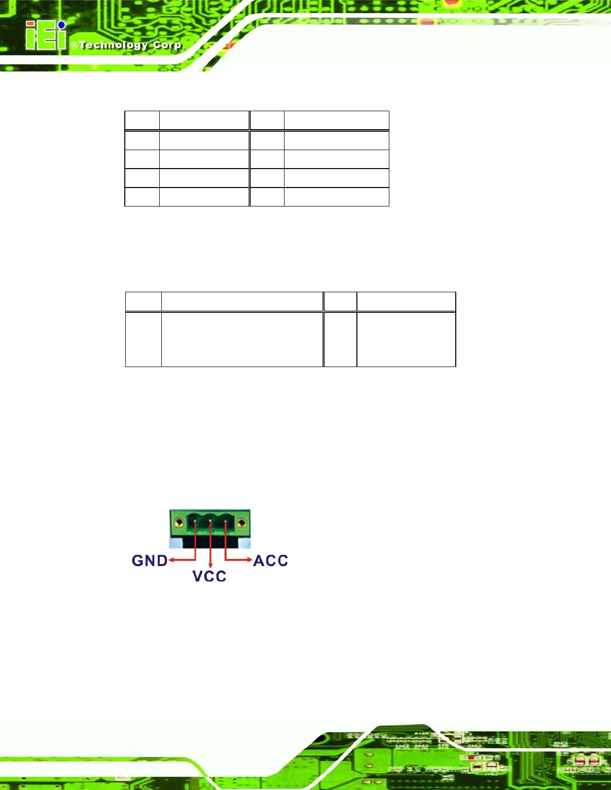
3.7.8 Power Input, 3-pin Terminal Block
The power connector connects the leads of a 9V~36V DC power supply into the terminal
block. Make sure that the power and ground wires are attached to the correct sockets of
the connector.
Figure 3-25: 3-pin Terminal Block Pinouts
3.7.9 Power Input, 4-pin DIN Connector
The power connector connects to the 10.5 V ~ 36 V DC power adapter.


