Installation and Configuration
9
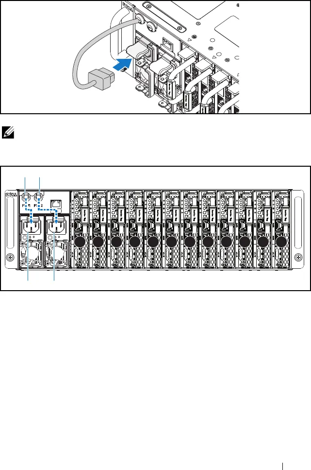
Figure 1-10. Connecting the Power Cable to the Power Supply Unit
Figure 1-11. Locating the Power Supply Unit Sockets
4
Push the sled into the system until flush with the case and the release latch
locks.
NOTE:
The correct configuration of the integral chassis AC power cables to the
power supply unit sockets is shown in the following illustration.
1 2 3 4 5 6 7 8 9 10 11 12
PSU1 PSU2
PSU1 PSU2
KTTDFA00.book Page 9 Thursday, September 26, 2013 11:31 PM


