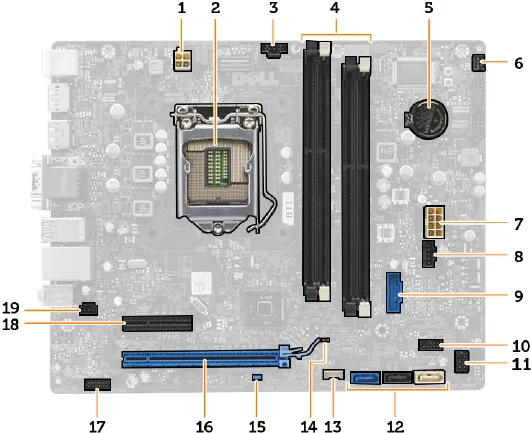
System Board Components
The following image displays the system board layout.
1. power connector
2. processor socket
3. system fan connector
4. memory module connectors
5. coin-cell battery
6. power switch connector
7. system power connector
8. system fan connector
9. front-USB 3.0 connector
10. front panel connector
11. HDD/ODD power connector
12. SATA connectors
13. internal speaker connector
14. RTC reset (RTCRST) jumper
15. password (PSWD) jumper
16. PCI Express x16 connector
17. front panel audio connector
18. PCI Express x4 connector
19. intrusion-switch connector
Removing the System Board
1. Follow the procedures in
Before Working Inside Your Computer
.
2. Remove the:
a) cover
b) front bezel
c) optical drive
d) drive cage
e) memory
f) heat sink assembly
g) expansion card(s)
h) power supply
3. Disconnect all the cables connected to the system board, and move the cables away from the chassis.
29


