the bracket's sliding tab on the drive-cage slide rail. Slide the bracket into place. Reinstall the screw you remove in step 4.
Figure 12. Inserting the Drive Bracket in the Chassis
NOTICE: You must match the colored strip on the EIDE cable with pin 1 on the drive's interface connector to avoid possible damage
to your system.
8. Connect one of the device connectors on the EIDE cable to the 40-pin interface connector on the back of the hard-disk drive
(see Figure 13).
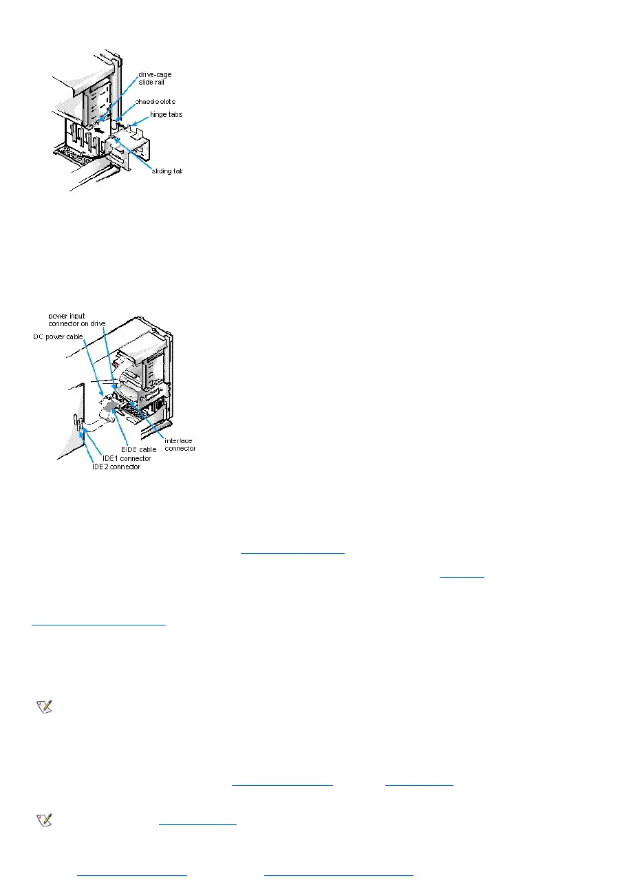
Figure 13. Attaching Hard-Disk Drive Cables
NOTICE: You must match the colored strip on the EIDE cable with pin 1 on the system board IDE connector to avoid possible
damage to your system.
9. If it is not already connected, connect the other end of the EIDE cable to the IDE connector on the system board.
To locate the system board IDE connector, see "System Board Features."
10. Connect a DC power cable to the power input connector on the back of the drive (see Figure 13).
Check all connectors to be certain that they are properly cabled and firmly seated.
11. Replace the computer cover, and reconnect your computer and peripherals to their power sources.
12. Turn on the peripherals connected to the computer.
13. Start the computer system.
l To boot the system from a diskette, insert a bootable diskette (such as an operating system installation or recovery diskette) into
diskette drive A, and turn on the computer.
l To boot the system from a CD, enter the System Setup program and set the Boot Sequence to CD-ROM First. Insert a bootable CD
(such as an operating system installation CD or the Dell ResourceCD) into CD-ROM drive, and turn on the computer.
14. Enter the System Setup program and update the Drives: Primary and Secondary options.