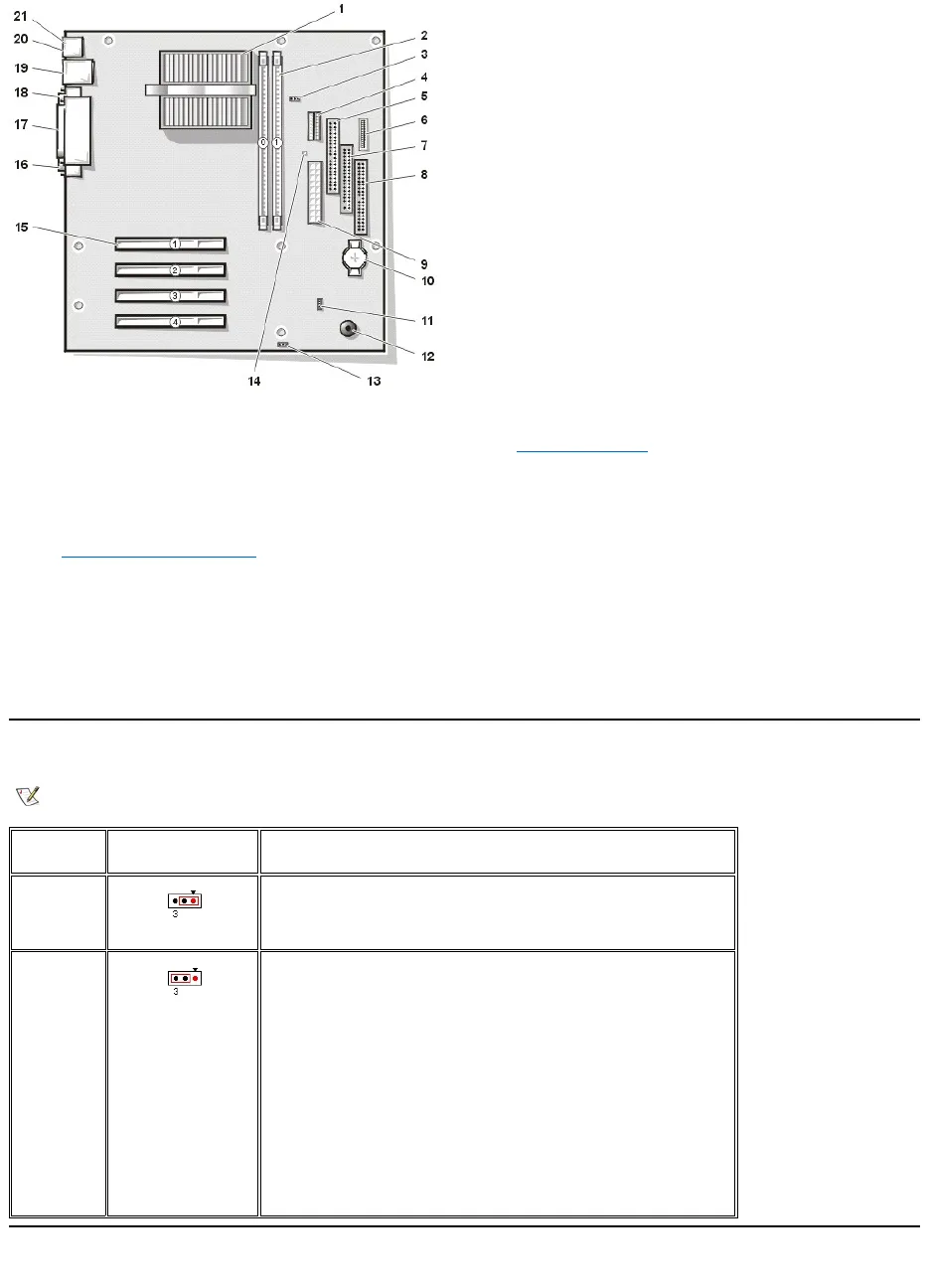
System Board Configuration Jumper
Power Supply
Microprocessor connector (J5H1)
Configuration jumper (J7A1)
3.3-V power connector (OPTIONAL POWER)
Card connectors (natural color) (PCIn)
Secondary IDE channel connector (SEC IDE)
Control panel connector (J9F2)
Parallel connector; sometimes referred to as LPT1
(PARALLEL)
Floppy drive interface connector (FLOPPY)
Primary IDE channel connector (PRI IDE)
Power input connector (POWER)
Keyboard connector (KEYBD)
Wakeup On LAN connector (WOL)
NOTE: The red dot in the jumper denotes pin 1.
Pins 1-2
jumpered
(Normal
mode)
In Normal mode, system setup settings and installed passwords are
retained when the computer starts up. In this mode, an automatic recovery
is attempted if the BIOS detects that any of its main blocks are corrupted.
Pins 2-3
jumpered
(Maintenance
mode)
Starting the computer with the jumper set in Maintenance mode
automatically starts the system setup program, adds the Maintenance
option to the menu bar, and displays the Maintenance screen. This
screen provides the following option.
NOTICE: Entering Maintenance mode returns all settings in the
system setup program to their defaults. Dell strongly recommends
that you record or print all current settings before entering this
mode so that you can correct them when the computer is reset to
Normal mode.
Clear All Passwords — Disables a forgotten password so that you can
access the computer and assign new passwords. For the complete
password procedure, see "Clearing Forgotten Passwords" in the
Solutions Guide.


