ASSEMBLY INSTRUCTIONS
Right hand (R.H.) and left hand (L.H.) are as observed
from the operating position.
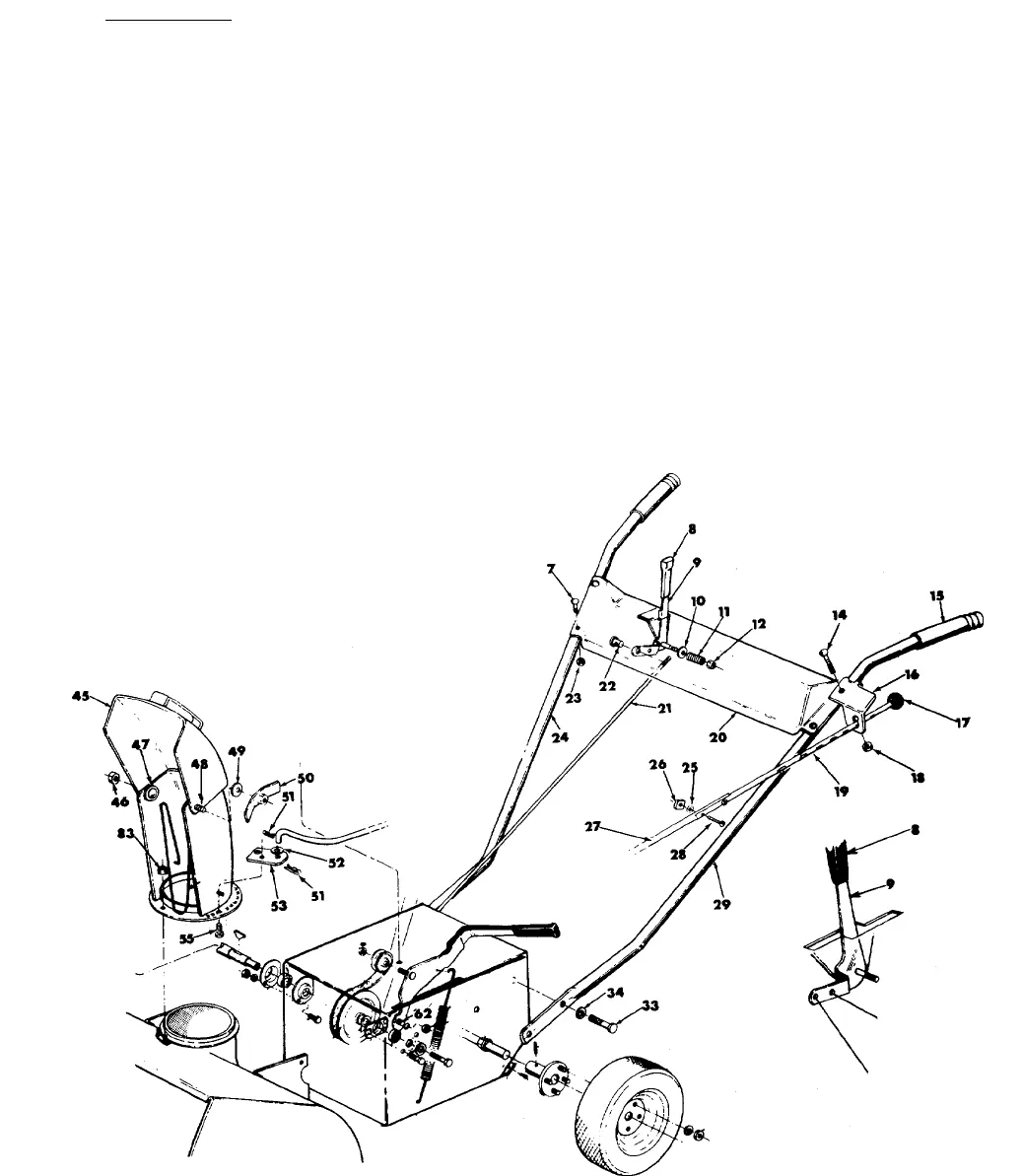
1. Assemble chrome handles (Ref. No. 24 and 29) to
the frame with four hex head cap screws %-16x %
long and four lock washers DO NOT TIGHTEN.
2. Assemble handle panel (Ref. No. 20) to the handles
with the four carriage bolts 14-20 x IVa Ig. and hex
locknuts 14-20 thd. Assemble handle panel so you
can read the instructions on the handle panel from
the operating position. LIFT HANDLE UP AS YOU
TIGHTEN ALL BOLTS AND NUTS ON THE HANDLE
ASSEMBLY.
4. Chute Crank. Assemble the chute crank (two parts)
into the two holes in the handle panel being sure
the rod passes through the chute control bracket.
Push the rod all the way through and assemble it
to the chute bracket with two cotter pins and flat
washers.
5. Remove the wing nut, washer, and carriage bolt
5/16-18 x% Ig. from the chute assembly. Lift the
deflector and reassemble. If the deflector will not
move, loosen the screw and nut slightly so it pivots
freely.
NOTE: Model 313-205 has no Reverse.
3. The linkage arm (Ref. No. 21) for the transmission is
located on the R.H. side of the frame. Pull the arm
back into reverse. (Towards the operator.) It may be
necessary to roll the snow thrower slightly until it
engages in the reverse position. Assemble the fer
rule to the shift lever handle use hole marked "20"
\ on the handle panel and screw in the shifting rod.
Adjust the rod by screwing it in or out until it fits
into the linkage arm on the side of the frame. Se
cure it with a cotter pin.
Use This Hole
20" Models
Use This Hole
26" Models


