4 D-302887
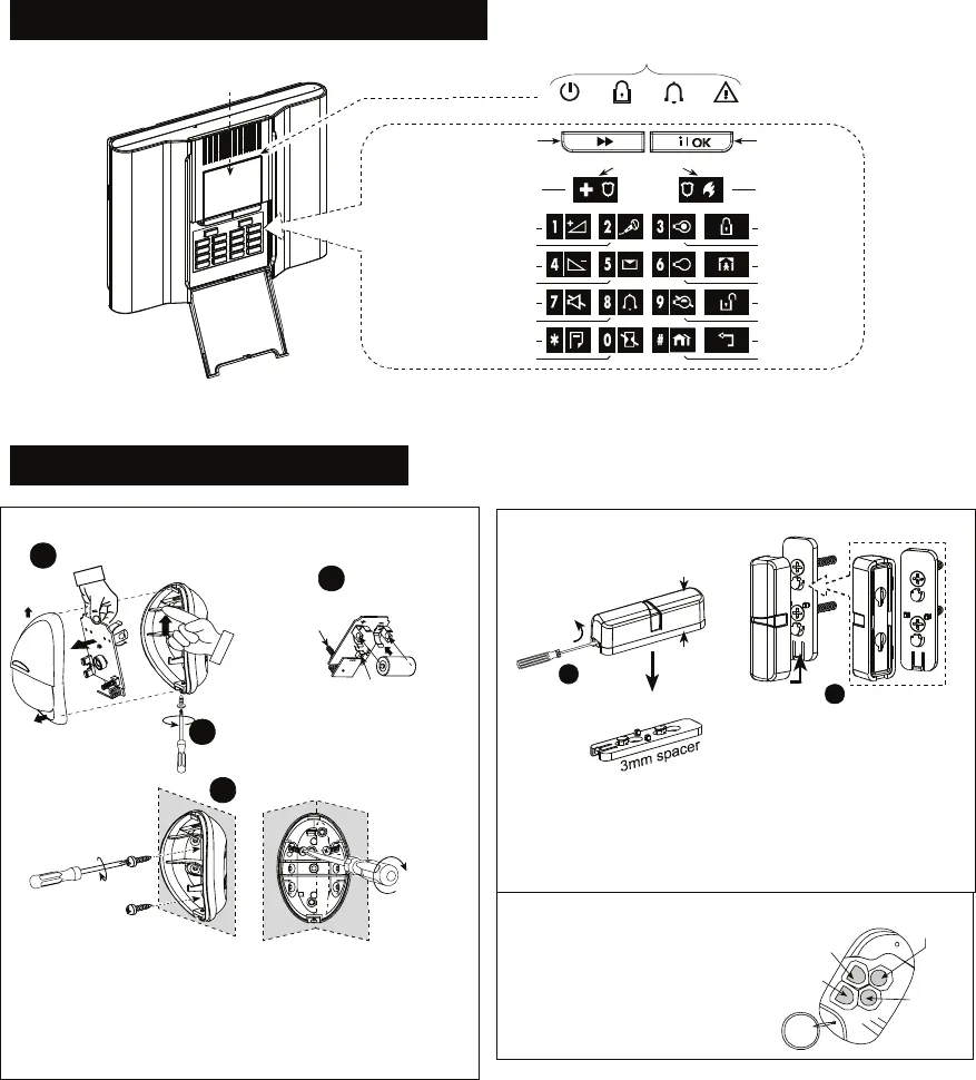
5. CONTROLS AND INDICATORS
VOLUME UP (*)
EMERGENCY
(Hold for 2 sec.)
PLAY MESSAGE (*)
VOLUME DOWN (*)
CHIME ON/OFF
MUTE SPEAKER (*) (**)
EVENT LOG
CANCEL ENTRY DELAY
RECORD MESSAGE (*)
ARM TROUBLECHIMEPOWER
PGM OUTPUT ON
PGM OUTPUT OFF
PGM CONTROL
PARTITION
ARMING “AWAY”
ARMING “HOME”
DISARMING
MOVE BACK
FIRE (Hold
for 2 sec.)
Press both
for panic
alarm
SHOW/OK
NEXT
INDICATORS
DISPLAY
Figure 5 - Controls & Indicators
6. DEVICES INSTALLATION
Fig. 6 - NEXT K9-85 MCW INSTALLATION
On surface
In corner
1
2
Push catch and remove board
3
Insert battery
Front Tamper switch
Back Tamper switch (option)
Release screw and
remove cover
4
Mounting
Notes
1. Keep away from heat sources.
2. Do not expose to air drafts.
3. Do not install outdoors.
4. Avoid direct sunshine.
5. Keep wiring away from power cables.
6. Do not install behind partitions.
7. Mount on solid stable surface
Fig. 7 - MCT-320 INSTALLATION
2
1
Remove spacer
Magnet
3mm
spacer
A.
Fasten the spacer to mounting
surface with 2 screws.
B. Locate the magnet on the
spacer at the correct direction and
push it upward.
Note
It is highly recommended to attach the transmitter to the top
of the door/window on the fixed frame and the magnet to the
movable part (door or window). Make sure that the magnet is
located not more than 6 mm (0.25 in.) from the transmitter’s
marked side.
Fig. 8 - MCT-234 USAGE
Pressing both AWAY + HOME
initiates a PANIC alarm.
DISARM
AWAY
AUX
HOME


