– 25 –
APPENDIX
APPENDIX
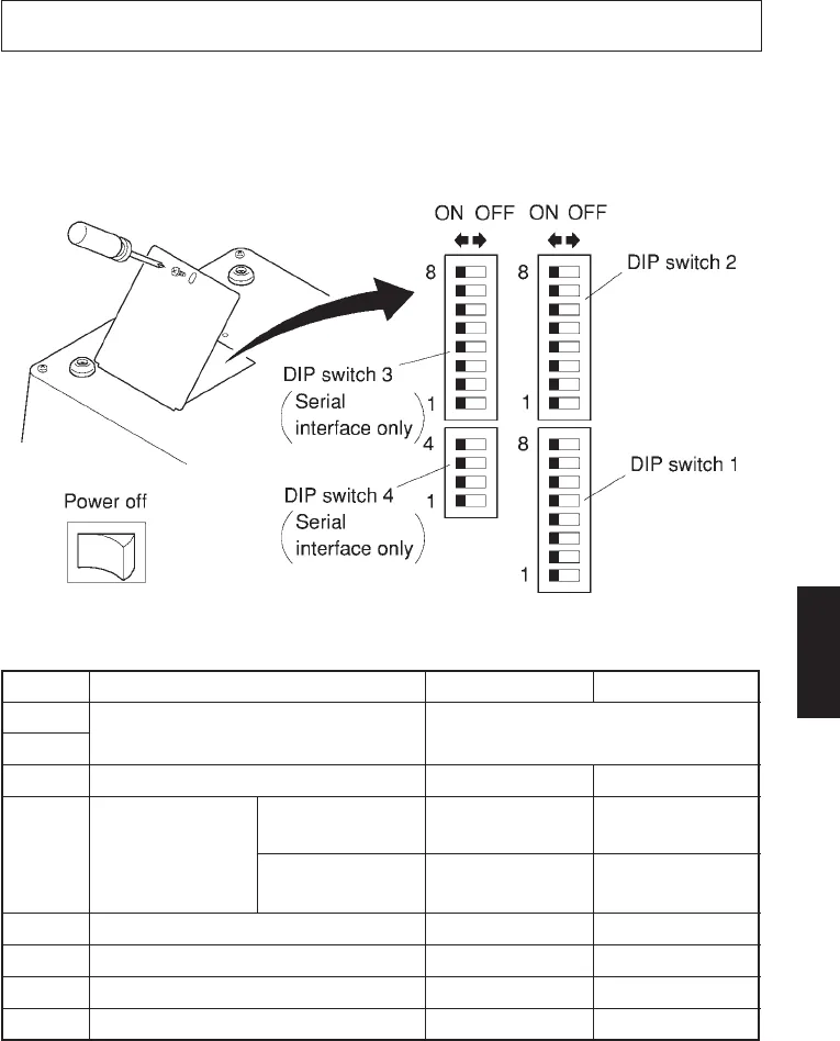
DIP Switch Setting
Each of the switches in the DIP switch array is factory preset to the “ON” position.
Be sure to turn the power for both the printer and host computer off before
changing the setting of the DIP switches.
DIP switch array
■ DIP-SW 1
Switch Function ON OFF
1-1
(Not used)
1-2
1-3 Control code CR Invalid Valid
1-4 When turning DC1, DC 3 Select Deselect
*1 the power on. mode
Addressable Deselect Select
mode *2
1-5 Setting the paper feed length 1/6-inch 1/8-inch
1-6 Setting the buffer size 4 K-bytes 256 bytes
1-7 Backed up RAM YES NO
1-8 Paper out detection function Valid Invalid
*1 If you use a parallel interface printer, Switch 1-4 is used for switching the auto
cutting control mode. For details, see Switch 3-4 described on the following
page. (SP342)
*2 The addressable mode is valid only when the optional RS-422A serial
interface is mounted.


