ENGLISH
7
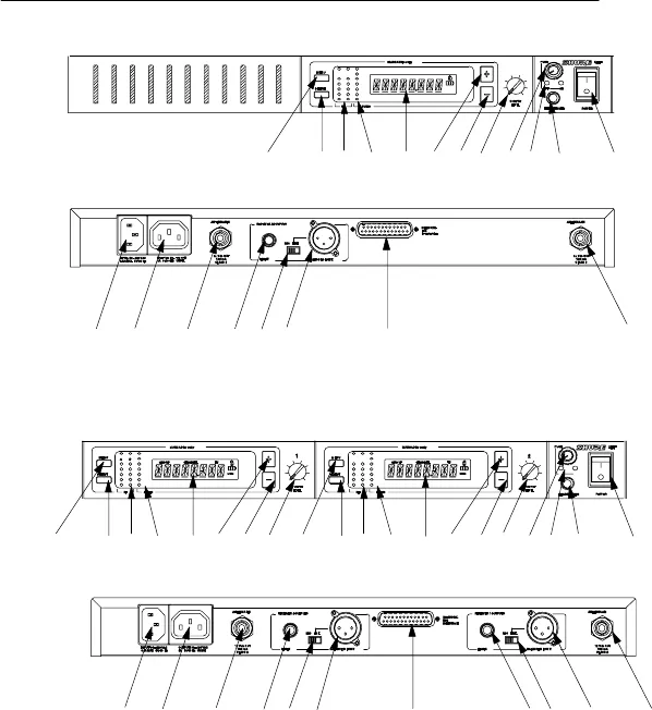
FIGURE 4
U4S Receiver
U4D Receiver
mn o pqr s
adbc e f gh ij k l
o
mn o pqr s
adbc e f g h ij k
l
abcdefg
h
opq r
U4S & U4D RECEIVER CONTROLS & CONNECTORS (FIGURE 4)
1. MENU Button: Press this button to access the main display menu.
2. SELECT Button: Press this button to choose or execute a displayed value or
function.
3. RF Level Indicators: Five LEDs per RF antenna channel glow to indicate RF sig-
nal strength. The more LEDs that glow, the stronger the received signal. If none
of these LEDs glow, no signal is being received.
4. Audio Level Indicators: These seven LEDs glow to indicate audio signal
strength. Green indicates normal operation. Amber indicates approaching over-
load condition. Red indicates excessively high audio levels. (Clipping occurs
within 4–6 dB when the red LEDs glow).


