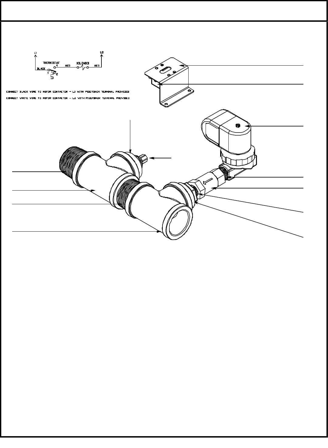
ITEM QTY DESCRIPTION Mfg. No.
1 1 Thermostat 5930-121-67-72
2 1 Thermostat Bracket 5700-022-73-72
3 1 Solenoid Valve 4810-100-09-18
4 2 Nipple, Close, 1/2: NPT, Brass 4730-207-15-00
5 1 Valve, Check, 1/2” 4820-002-55-77
6 1 Reducer, 1-1/2” to 1/2” 4730-002-55-75
7 2 Tee, 1-1/2” x 1-1/2” x 1-1/2” 4730-011-69-93
8 2 Nipple, 1-1/2”, Close, Brass 4730-207-40-00
9 1 Reducer, 1-1/2” to 1/4” 4730-002-55-76
10 1 Modified Compression Fitting 5700-001-16-52
1 Complete Kit 6401-002-44-07
DRAIN QUENCH SYSTEM (CONVEYOR SERIES)
To Dishmachine Drain
To Drain
To Cold Water Supply
Schematic
1
2
3
4
5
4
6
7
8
7
8
9
10
From the existing drain, attach the two additional Tees (Item 7) using the 1-1/2” NPT Close Nipples )Item 8). Tighten the Reducers
(Items 6 & 9) into the Tees as shown above. Attach the Modified Compression Fitting (Item 10) into the 1-1/2” to 1/4” Reducer (Item
9). Position the bulb of the thermostat (Item 1) so that it rests approximately 1/4” from the bottom of the Tee (Item 7). Tighten the
Modified Compression Fitting (Item 10) as required.
Mount the Thermostat (Item 1) ti the tub using the Thermostat Bracket (Item 2) and set it for 120
°
F - 140
°
F. Install the Solenoid Valve
(Item 3) to the second Tee (Item 7) and then attach to the incoming cold water line. Use pipe dope or thread tape as required to pre-
vent any leaks.
49


