D1
D2
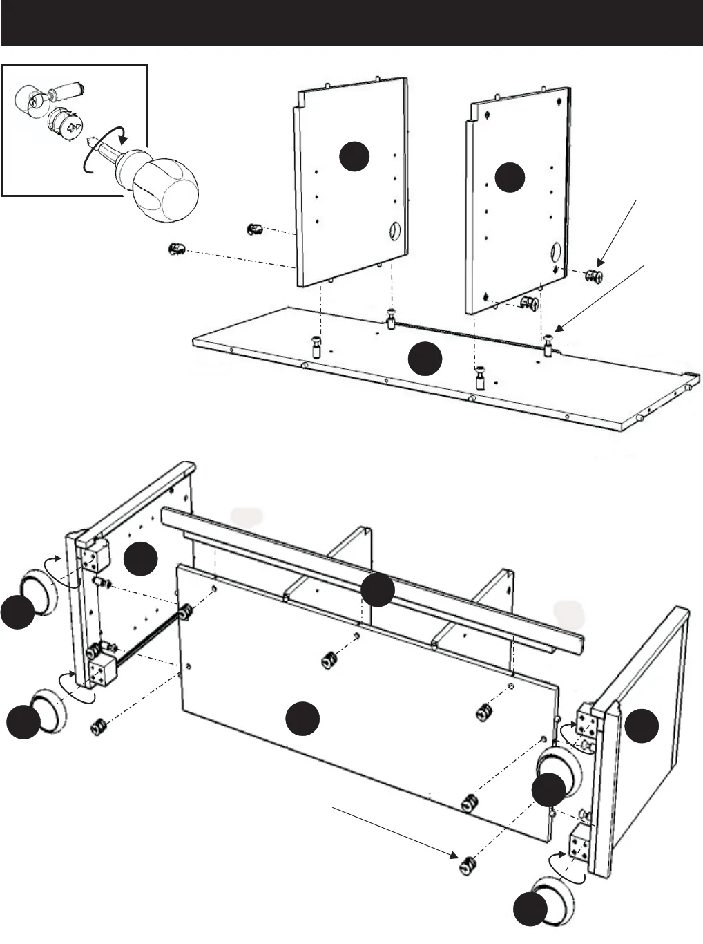
STEP 3
Assembly Instructions 3/4
Cam Lock
Screw
Cam Lock
Figure 1
E
E
STEP 2
Attach Middle Panel (D1)
and (D2) onto Base (E)
with Cam Locks (see Figure 1).
B
C
F
G
G
G
G
Cam Lock
Attach Plinth (F) to the unit with Cam Locks.
Attach Side Panel (B) and (C) to the unit with Cam Locks.
Attach Legs (G) into the pre-drilled holes of Base (E) and tighten.


