Assembly Instructions
2
IMPORTANT
* Please keep Hex Wrench in a safe place as you may need to tighten up the Head Cap Bolts in the future.
* Do not tighten up all the bolts until each part is properly assembled.
* Use a soft cloth between these parts and the fl oor.
/5
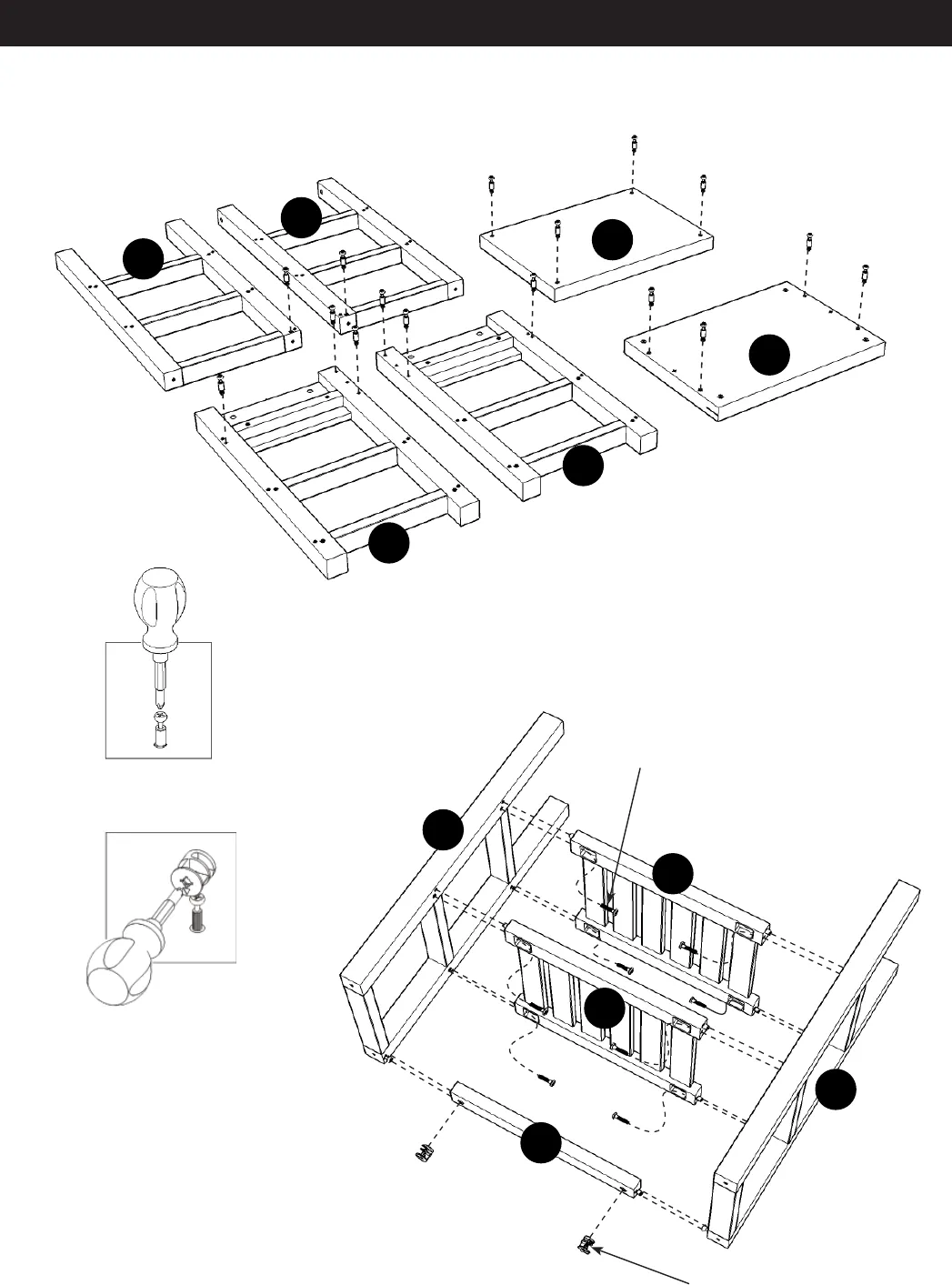
STEP 1
Insert Cam Lock Screws into pre-drilled holes of
Top (A), Top (B), Frame (C), Frame (D), Frame (F)
and Frame (G), then tighten.
(See fi gure 1)
STEP 2
Attach Shelves (J) to Frame (C) with Head Cap Bolts .
Attach Back Stretcher (E) to Frame (C) with Cam Locks.
(See fi gure 2)
Attach Frame (D) to unit with Head Cap Bolts and Cam Locks.
A
B
C
D
J
J
E
F
C
D
G
Figure 1
Head Cap Bolt
Cam Lock
Figure 2


