P
P
4
4
V
V
T
T
G
G
-
-
M
M
13
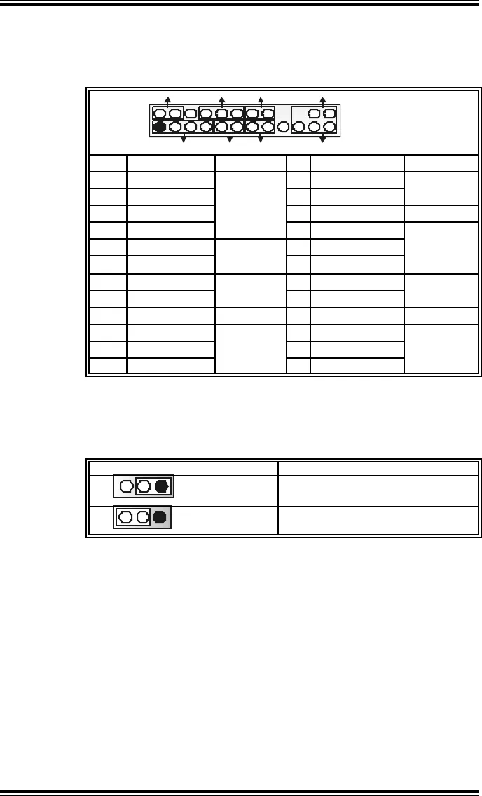
Front Panel Connector: JPANEL1
This 24-pin connector includes Power-on, Reset, HDD LED, Power
LED, Sleep button, speaker and IrDA Connection. It allows user to
connect the PC case’s front panel switch functions.
SPK
PWR_LED
HLED
SLP
RST
224
IR
1
23
IRON/OFF
JPANEL1
Pin Assignment Function Pin Assignment Function
1 +5V 2 Sleep control
3 N/A 4 Ground
Sleep button
5 N/A 6 N/A N/A
7 Speaker
Speaker
Connector
8 Power LED (+)
9 HDD LED (+) 10 Power LED (+)
11 HEE LED (-)
Hard drive
LED
12 Power LED (-)
Power LED
13 Ground 14 Power button
15 Reset control
Reset
button
16 Ground
Power-on
button
17 N/A 18 Key
19 N/A 20 Key
21 +5V 22 Ground
23 IRTX
IrDA
Connector
24 IRRX
IrDA
Connector
Close CMOS Jumper: JCMOS1
By placing the jumper on pin2-3, it allows user to restore the BIOS
safe setting and the CMOS data, please carefully follow the
procedures to avoid damaging the motherboard.
JCMOS1 Assignment
13
Pin 1-2 close
Normal Operation (Def ault).
13
Pin 2-3 close
Clear CMOS data.
※ Clear CMOS Procedures:
1. Remove AC power line.
2. Set the jumper to “Pin 2-3 close”.
3. Wa i t for fi ve seco nds.
4. Set the jumper to “Pin 1-2 close”.
5. Power on the AC.
6. Reset your desired password or clear the CMOS data.


