10
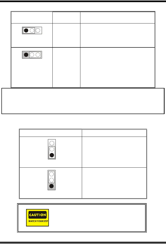
Power Source Selection for USB: JUSBV1/ JUSBV2/ JUSBV4
JUSBV1/JUSBV2/
JUSBV4
Assignment Description
1 3
Pin 1-2 close
+5V
JUSBV1: 5V for JUSB1 port
JUSBV2: 5V for JUSBLAN1 port
JUSBV4: 5V for JUSB2 port
1 3
Pin 2-3 close
+5V Standby
Voltage
JUSBV1: JUSB1 port powered with
standby voltage of 5V
JUSBV2: JUSBLAN1 port powered with
standby voltage of 5V
JUSBV4: JUSB2 port powered with
standby voltage of 5V
Note: 1. In order to power-on USB devices function, “JUSBV1/JUSBV2/
JUSBV4” jumper cap should be placed on pin 2-3 respectively.
2. For S3 mode, “JUSBV1/ JUSBV2/ JUSBV4” jumper cap should be
placed on pin 2-3 respectively.
Clear CMOS Jumper: JCMOS
JCMOS Assignment
1
3
Pin 1-2 Close
Normal Operation (default)
1
3
Pin 2-3 Close
Clear CMOS Data
The following procedures are for resetting the
BIOS password. It is important to follow these
instructions closely.


