Product Description
37
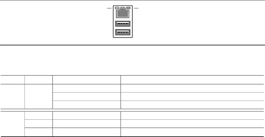
1.11.2.2 RJ-45 LAN Connector with Integrated LEDs
Two LEDs are built into the RJ-45 LAN connector (as shown in Figure 13). Table 9 describes the
LED states when the board is powered up and the Gigabit LAN subsystem is operating.
Green LED
Green/Yellow LED
OM16513
Figure 13. LAN Connector LED Locations
Table 9. LAN Connector LED States
LED Color LED State Condition
Off LAN link is not established.
On LAN link is established.
Left Green
Blinking LAN activity is occurring.
N/A Off 10 Mbits/sec data rate is selected.
Green On 100 Mbits/sec data rate is selected.
Right
Yellow
On
1000 Mbits/sec data rate is selected.
1.11.3 Alert Standard Format (ASF) Support
The boards provide the following ASF support for the onboard 10/100/1000 LAN subsystem, PCI
Express x1 bus add-in LAN cards, and PCI Conventional bus add-in LAN cards installed in PCI
Conventional bus slot 2:
• Monitoring of system firmware progress events, including:
⎯ BIOS present
⎯ Primary processor initialization
⎯ Memory initialization
⎯ Video initialization
⎯ PCI resource configuration
⎯ Hard-disk initialization
⎯ User authentication
⎯ Starting operating system boot process
• Monitoring of system firmware error events, including:
⎯ Memory missing
⎯ Memory failure
⎯ No video device
⎯ Keyboard failure
⎯ Hard-disk failure
⎯ No boot media
• Boot options to boot from different types of boot devices
• Reset, shutdown, power cycle, and power up options


