FRONT CONTROL PANEL
①. POWER Indicator
When the POWER switch ⑯ is ON, the LED will turn GREEN. When the battery
voltage level becomes too low for proper operation, the LED will turn RED. When
this happens, replace the batteries with fresh "AA" alkaline batteries.
②. Channel 1, 2, 3 & 4 Input LEVEL Controls
Each knob controls the input volume of the microphone connected to the
corresponding INPUT ⑬. Zero is the lowest (quietest) setting while 10 is the highest
(loudest). For the best sound with the lowest possible noise, increase the input level
control until the corresponding VU Meter ⑧ peaks at 0 dB.
③. Channel 1, 2, 3 & 4 PAN Controls
Each channel of the FMX-42a has an adjustable PAN control (the outer-rim at the
base of the Input LEVEL control ②). When the PAN Control is in the center position,
an equal amount of sound will come from OUTPUT L ⑰ and OUTPUT R ⑱ for any
microphone or line-level input connected to the corresponding INPUT ⑬. Moving
the PAN control left will decrease the sound output in the Right channel. Moving the
PAN control right will decrease the sound output in the Left channel.
④. MASTER Level Control
The MASTER knob controls the overall volume of all connected sources
(microphones and/or line-level devices). For the best sound with the lowest possible
noise, try to keep this control set at its midpoint while maintaining the VU Meters ⑧
at the 0 dB range with the input LEVEL controls ②.
⑤. Channel 1, 2, 3 & 4 LIMITER Switch
Each INPUT channel ⑬ has a switchable LIMITER. After setting the input LEVEL ②,
turn this switch to ON. The LIMITER circuit acts as a safety and reduces the
possibility of overload distortion from very loud sounds without affecting normal
sound volume. If you prefer the overall sound quality of the mixer without the
LIMITER circuit engaged, leave the switch OFF.
⑥. Channel 1, 2, 3 & 4 HPF (High Pass Filter) Switch
Each INPUT channel ⑬ has a switchable High Pass (= Low Cut) Filter. When turned
on, it will cut input signals lower than 100Hz. This filter is useful for removing
unwanted low frequencies, such as wind and air-conditioning noise. For most
applications, engaging the High Pass Filter will improve overall sound quality.
⑦. Input PEAK Level Indicators
Each INPUT channel has 2 PEAK Level Indicators on the left side of the LEVEL
control knob ②.These Indicators are provided to help set precise input LEVEL
adjustments. The lower LED indicates the level of the input electronically prior to the
LEVEL control while the upper LED indicates the level electronically after the LEVEL
control. The lower LED lighting RED indicates that the item connected to the mixer's
INPUT ⑬ has a signal that is too high and should be reduced either by changing the
INPUT LEVEL switch ⑭ setting or at the device itself. The upper LED should only
light RED occasionally. If this LED stays lit continuously, lower the input LEVEL ②
and/or change your INPUT LEVEL ⑭ settings. These LEDs help reduce signal
overload and distortion.
⑧. VU Meters L and R
The VU Meters will show either the output volume level of LINE OUT ⑰&⑱ or input
volume level of CAMERA RETURN ⑳, whichever is selected by the Monitor
⑳
26
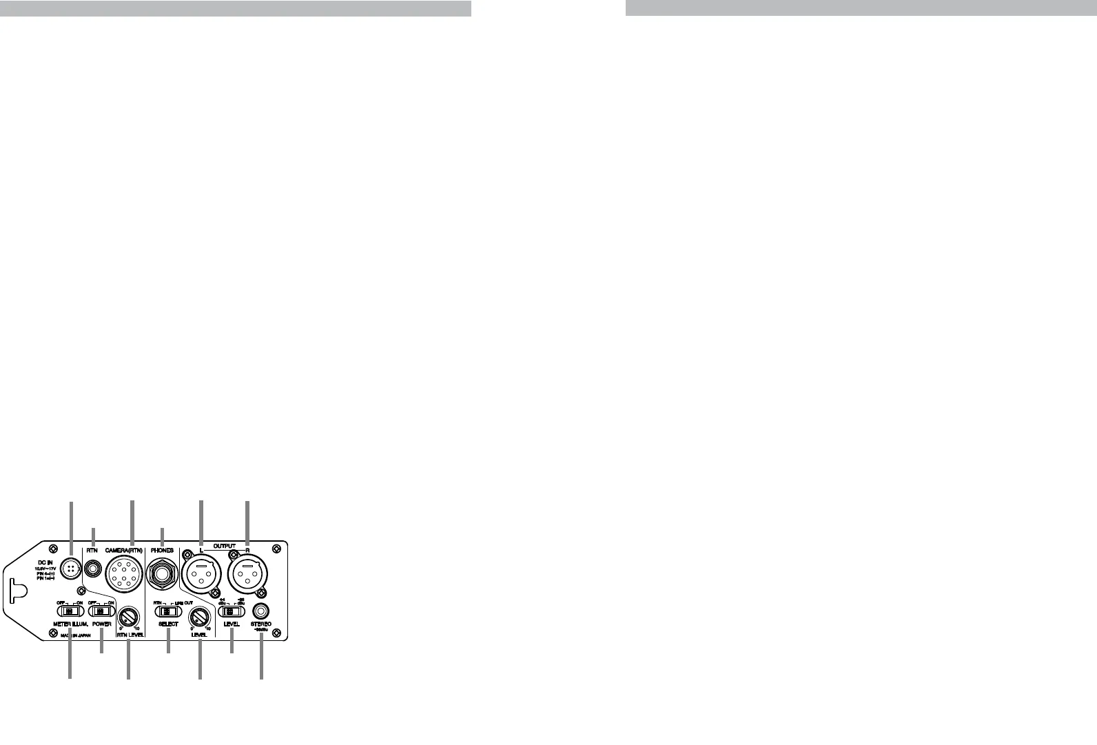
RIGHT-SIDE OUTPUT/CONTROL PANEL
⑳.Monitor SELECT Switch
To SELECT either LINE OUT ⑰&⑱ output signals or CAMERA(RTN) ⑳ input signals
for the monitor PHONES output ⑳.
⑳.LEVEL Volume Control
Controls the volume level of the monitor PHONES output ⑳. Zero is the lowest(quietest)
setting and 10 is the highest (loudest).
⑳.METER ILLUM(ination) Switch / Turn this switch ON to light up the VU Meters⑧.
⑳.DC IN Connector
For external powering of the mixer, connect a 12V AC adaptor to this input. It is a
4-pin Hirose connector and an optional AC adaptor, part number BC-27, is available. Call
Azden for details.
Maximum rating of the power supply must not exceed 12 volts DC, 350mA.
*Required connecting plug: Hirose HR10A-7P-4P
⑳.CAMERA(RTN) Input/Output Connector
This Hirose 10-pin connector allows you to connect your video camera and the mixer to
send the LINE OUT output signals and to receive the RETURN input signals simultaneously.
It will require the Hirose 10-pin plug (part #RM15TD-10P). Using this connector will not
cancel out the OUTPUT L & R ⑰&⑱. The LINE OUT output level can be set at +4 dBu
(LINE output) or -36 dBu (MIC output) by the LEVEL selector ⑳.
Connector Pin Configuration
⑳.RTN Mini-Jack
A 3.5mm unbalanced stereo input jack for return signals. The volume level can be adjusted
by the RTN LEVEL volume control ⑳. Plugging a cable into this jack will cancel out the
CAMERA(RTN) ⑳ input.
⑳.RTN LEVEL Volume Control / Controls the volume LEVEL of the RETURN input.
⑳
21
⑳
26
⑳
21
⑳
20
⑳
28
⑳
26
Pin # 1 ----- LINE OUT L (+) 6 ----- NC
2 ----- LINE OUT L (-) 7 ----- RTN IN L (+)
3 ----- LINE OUT R (+) 8 ----- NC
4 ----- LINE OUT R (-) 9 ----- GND
5 ----- RTN IN R (+) 10 --- GND
⑯
⑰ ⑱
⑲⑳
⑳
⑳
⑳
⑳
POWER
Switch
OUTPUT
Connector L
OUTPUT
Connector R
STEREO Mini-
Connector Output
LEVEL
Selector
⑳
Monitor
SELECT
Switch
MONITOR
PHONES
LEVEL
Volume Control
METER
ILLUMINATION
Switch
DC IN
Connector
21
⑰
⑳
CAMERA(RTN)
Connector
RTN
Mini-Jack
27
23
⑳
RTN
LEVEL
Volume Control
28
24
25
22
26
⑳
22
⑳
23
⑳
24
⑳
25
⑳
26
⑳
27
⑳
28


