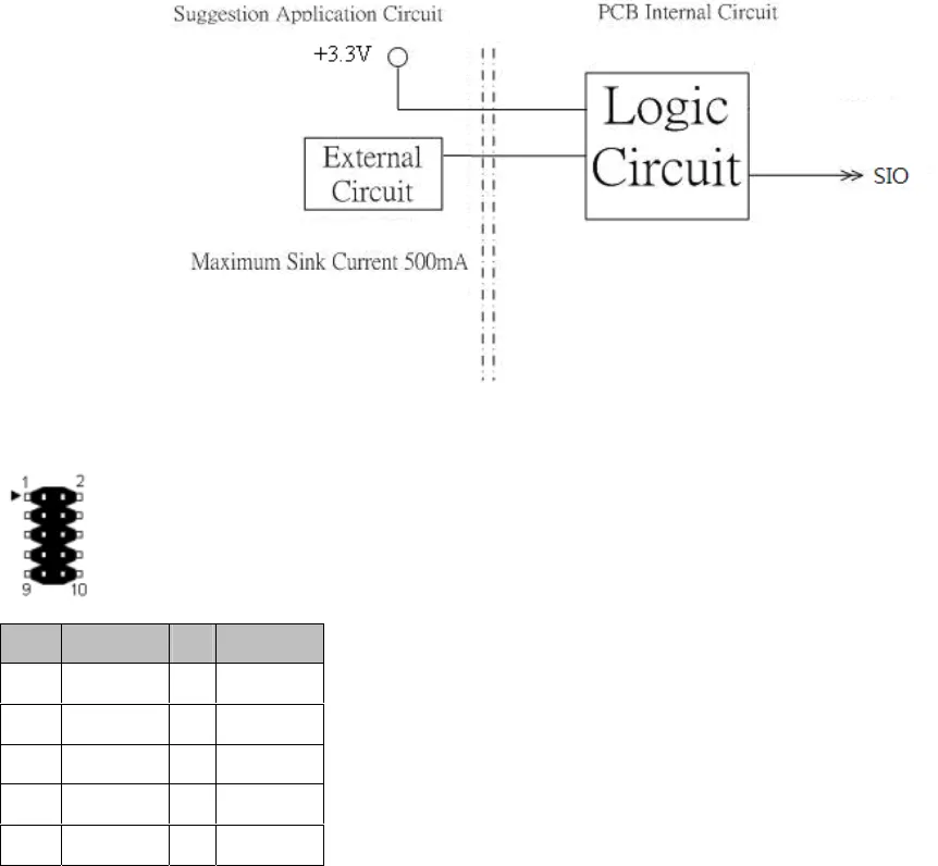
4.3 Digital Outputs
There are 4 clamped diode protection digital outputs on GPIO1 connector(pin header). You can
control the output status of these digital outputs through the software API. The four digital
outputs are capable sink maximum 500 mA current for each channel and maximum output
voltage is 12V. The output reference voltage of device, please connect to GPIO1 VCC3V(Pin2).
These digital outputs are general purpose outputs. The detailed information please refers to
Software Programming Guide for how to use the API.
Following diagrams state how to connect the digital outputs to devices on the embedded
system.
Note.
1. Output Default set: Low
2. Output Type: Open drain MOSFET driver
3. It needs a Schottky Diode to parallel connect with any inductive component, such as relay
and bulb.
GPIO1 Pin Define:
PIN SIGNAL PIN SIGNAL
1
GPO 1
2
+VCC3
3
GPO 2
4
GPI 1
5
GPO 3
6
GPI 2
7
GPO 4
8
GPI 3
9
GND
10
GPI 4
26


