Design Guide
3
36" Frame to
Frame Width
*84" From
Floor to
Top Frame
35"
Case Width
*83-1/2"
at
Rear
25-3/8" Framed Models
25-3/4" Stainless Steel Models
Case Depth
Depth Including Handles:
26-7/8" Framed Models
27-3/4" Stainless Steel Models
28-11/16" Professional Models
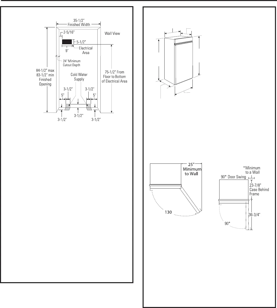
THE INSTALLATION SPACE
Water And Electrical Locations
Electrical and water supply must be located as shown.
The Cutout Depth Must Be 24” Minimum
7KHXQLWZLOOSURMHFWIRUZDUGVOLJKWO\EH\RQGDGMDFHQW
cabinetry, depending on your installation.
Cutout Depth Beneath a Soffit:
When installed beneathh a soffit, the soffit cannot
H[FHHGWKHµLQVWDOODWLRQGHSWKVKRZQ7KHWRSFDVH
trim overlaps the bottom of the soffit.
Additional Specifications
$YROW+]RUDPSSRZHUVXSSO\
is required. An individual properly grounded branch
circuit or circuit breaker is recommended. Install
a properly grounded 3-prong electrical receptacle
recessed into the back wall. Electrical must be
located on rear wall as shown.
Note: GFI (ground fault interrupter) is not
recommended.
:DWHUOLQHFDQHQWHUWKHRSHQLQJWKURXJKWKH
IORRURUEDFNZDOO7KHZDWHUOLQHVKRXOGEHµ2'
FRSSHUWXELQJRU*(4XLFN&RQQHFW
™
kit between the
cold water line and water connection location, long
enough to extend to the front of the unit. Installation
of an easily accessible shut-off valve in the water line
is required.
DIMENSIONS AND CLEARANCES
6KLSSLQJKHLJKW7KH
product can be adjusted
to fit into a cutout that
LVµPLQWRµ
PD[KHLJKW1RWHWKDW
the top case trim
DWWKHIURQWLVµKLJKHU
and will overlap upper
FDELQHWU\RUVRIILW8VH
leveling legs and wheels
for a maximum 1” height
adjustment.
Product Clearances
7KHVHXQLWVDUHHTXLSSHGZLWKDSRVLWLRQGRRUVWRS
7KHIDFWRU\VHWGRRUVZLQJFDQEHDGMXVWHGWR
if clearance to adjacent cabinets or walls is restricted.
Order WX14X99 door stop for precise settings between
90° and 130°.
130° Door Swing 90° Door Swing
7KHILQLVKHG
cutout width
must be
µ
Allow 25” minimum clearance for a full
130° door swing. Allow 15” for pan removal.
For a 90° door swing, allow 4” minimum clearance
to a wall for framed and stainless steel models.
Allow 5” minimum clearance for professional models.
If the 90° doorstop position is used, pan access
is maintained but pan removal is restricted.
See illustrations pages 5 and 6 to determine door swing
interaction with adjacent cabinets or countertops.
*4” stainless and trimmed
models. 5
” Pro models.


