ST700 GENERAL HANDBOOK
667/HB/27880/000 Page 66 Issue 8
Softwire Kit Cableform
667/1/27863/100
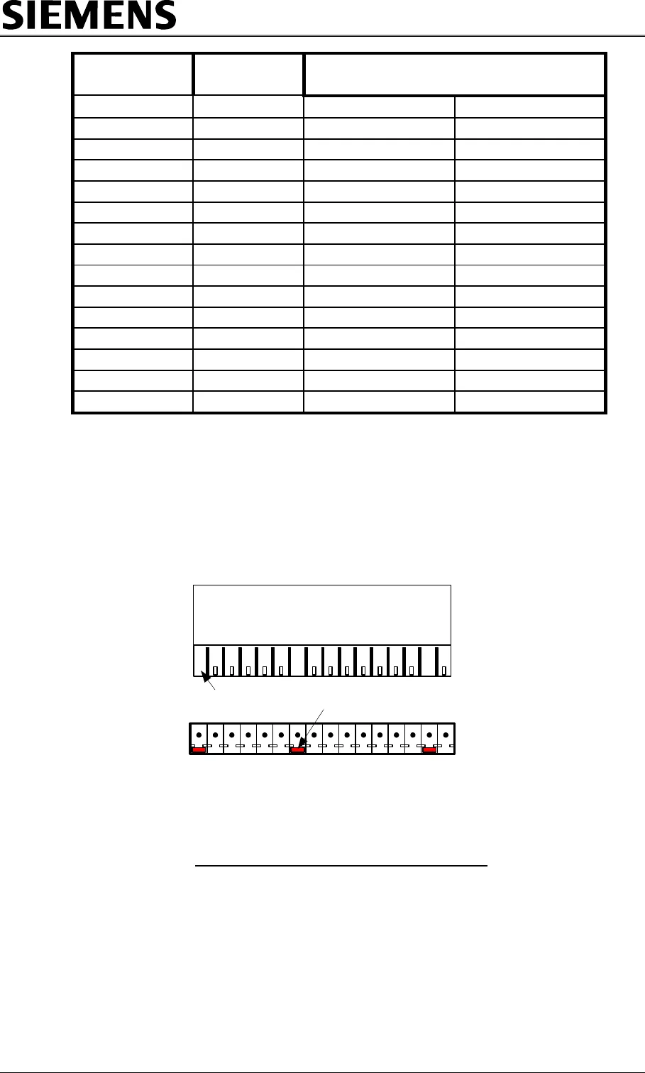
Coding Details: The plug mount connector on the CPU PCB PL6 has coding pins 1,
7 and 15 fitted, with the cable fitted socket connector that mates
with PL6 having coding ridges 1, 7 and 15 removed. This coding
prevent the incorrect connection between PL6 and PL7. For more
details see the following diagram:
PL6 on PCB
Mating Half PL6
1 7 15
Coding for PL6
Coding Ridge
Removes in 3
positions
Coding Pin
Inserted in
3 Positions
Figure 15 – Connector PL6
5.14 REGULATORY SIGNS MONITORING
The ST700 Rack Assembly does not cover regulatory signs and their associated
monitoring. There is a fuse position labelled „F3 Detector‟ which could be used to
supply regulatory signs if required. Their monitoring would require standard current
coils to be connected to the external analogue inputs.


