38 U25339-J-Z126-1-7600
General frame structure Standard processing in SVP mode
6.2.1 System status messages in line 22
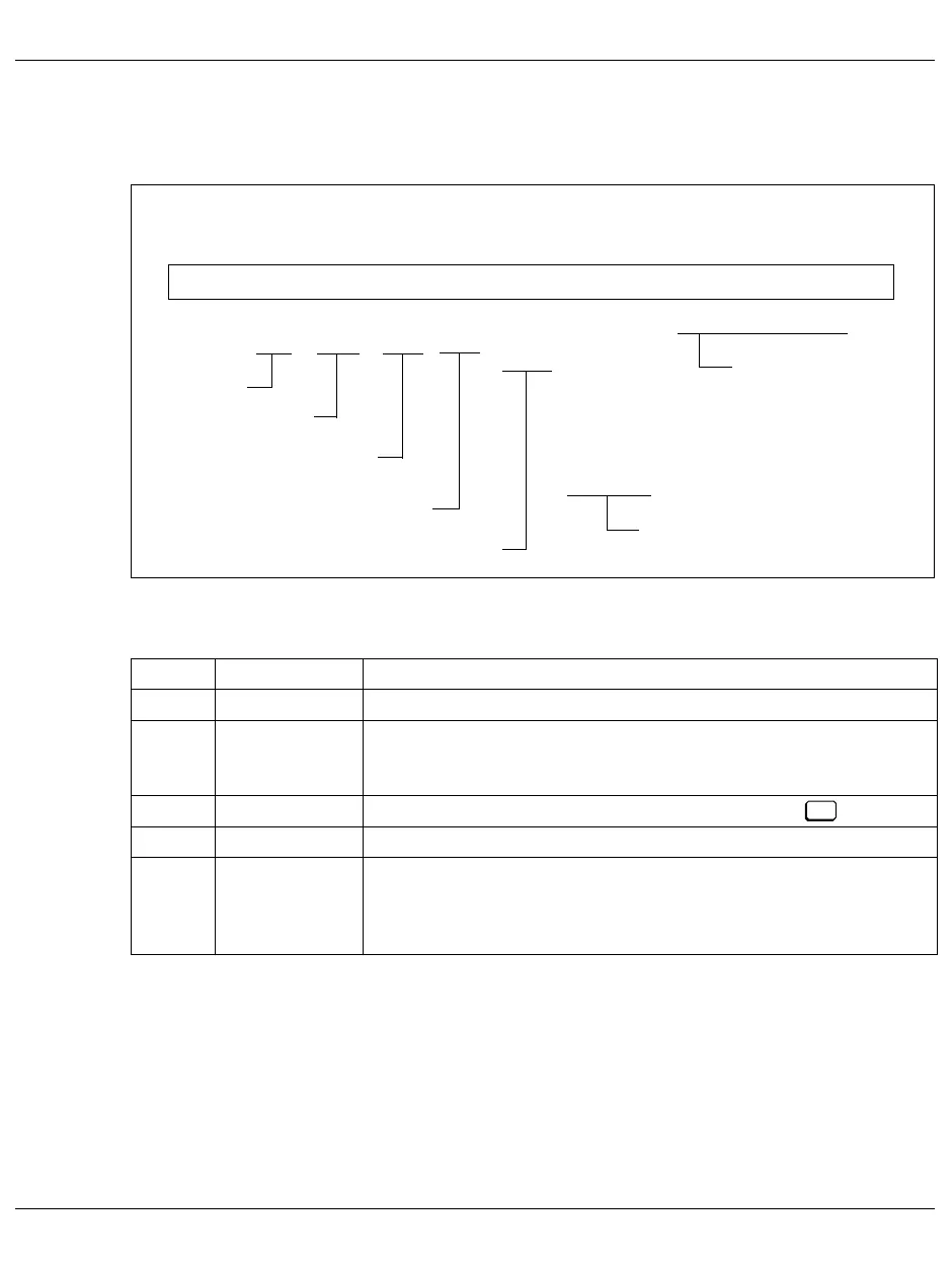
Figure 11: Format of the status display in line 22
Meaning of the status information in line 22:
Column Symbol Meaning
16 - 19 CL -n Cluster ID of the S130; normally CL - 0
22 - 27 none
HOST
GUEST
The system is operated in BS2000-NATIVE mode.
The selected CPU is occupied by the VM2000 monitor system.
The selected CPU is occupied by a VM2000 guest system.
28 - 32 CPU - n Display of the selected CPU (n = 0 - 7); selection with key.
33 - 37 CHP - n Display of the selected channel processor; display is usually CHP - 0.
40 -45 none
CLKSTP
I-STEP
H-STOP
The system is in the normal state.
The system is in the clock-stop state.
The system is in the instruction step state.
The system is in the hardware stop state.
12345678
SYS-DOWN
CL-STOP
CHK-STOP
COMP-STOP
STOP
PSW-LOOP
WAIT
RUN
LOAD
I-STEP
CLKSTP
.... + .... 0 .... + .... 0 .... + .... 0 .... + .... 0 .... + .... 0 .... + .... 0 .... + .... 0 .... + .... 0
CHP-n
CPU-n
HOST
GUEST
CL-n
PSW = xxxxxxxx xxxxxxxx
Cluster ID
HOST/GUEST
Target CPU
Target CHP
Rate control
System states
PSW contents
H-STOP
P16


