3
2.)
Install the mounting plate using ½” hardware. Attach to structural channel
or a solid mounting surface. Be sure the plate is level front-to-back and
side-to-side.
3.)
Add a plumb bob to the mounting plate at the indicator hole and hang the
bob down to ceiling. This is the center point for the hole cutout location for
the microphone assembly.
4.)
Cut a 1.75” hole in the ceiling aligned with the plumb bob.
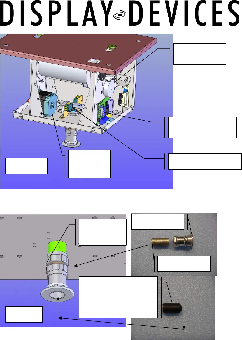
Upper piece
Fixed in lift
¾ “Conduit
Ceiling Bezel
Limit switch activation
mechanism and
factory-installed
weight
Upper Limit switch
Brake
Mechanism
Microphone Lift
control board
Figure 2
Figure 3
Stepper
Motor


