iDP-562 User’s Manual
CITIZEN 10
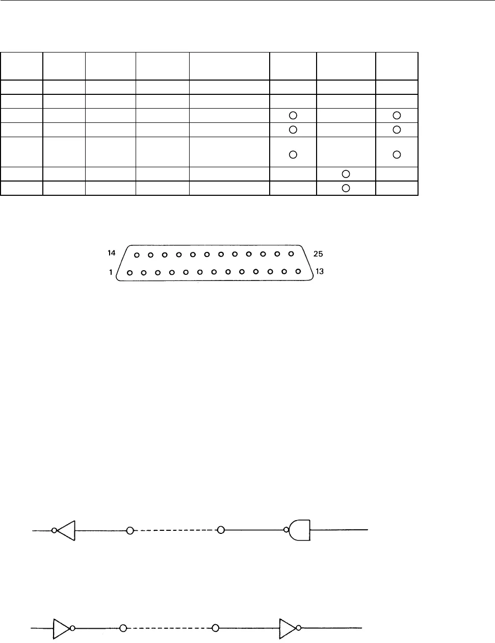
5.3 Connectors and Signals
Signal Return Signal Direction Function RS232C CURRENT TTL
Pin Line Name of Signal LOOP
1 FG Frame GND
7 SG GND
3RD
A → B
Input DATA
20 DTR
←
BUSY signal
14 FAULT
←
ALARM signal
25 23 RD
→
Input DATA
17 24 DTR
←
BUSY signal
A: Computer
B: Printer
Notes:
1. Signal of RS-232C conforms to EIA RS-232C level.
2. Signal of CURRENT LOOP should be restricted within 10 ~ 20 mA.
3. Keep signal pin No. 3 at MARK status when no transfer of DATA.
4. Selection of modes, those are RS-232C, CURRENT LOOP and TTL, can be made by the preset jumper
(Please refer to ‘Setting of Preset Jumper’).
Compatible Connector (D-Subconnector):
* Printer: 17LE-13250 (AMPHENOL or equivalent)
* Cable Side: 17JE-23250 (AMPHENOL or equivalent)
5.4 Interface Circuit
RS-232C
Input (RD)
Printer side Computer side
Equivalent to 232
Output (DTR FAULT)
Equivalent to 232


