Receiver Controls and Features
Liberator One
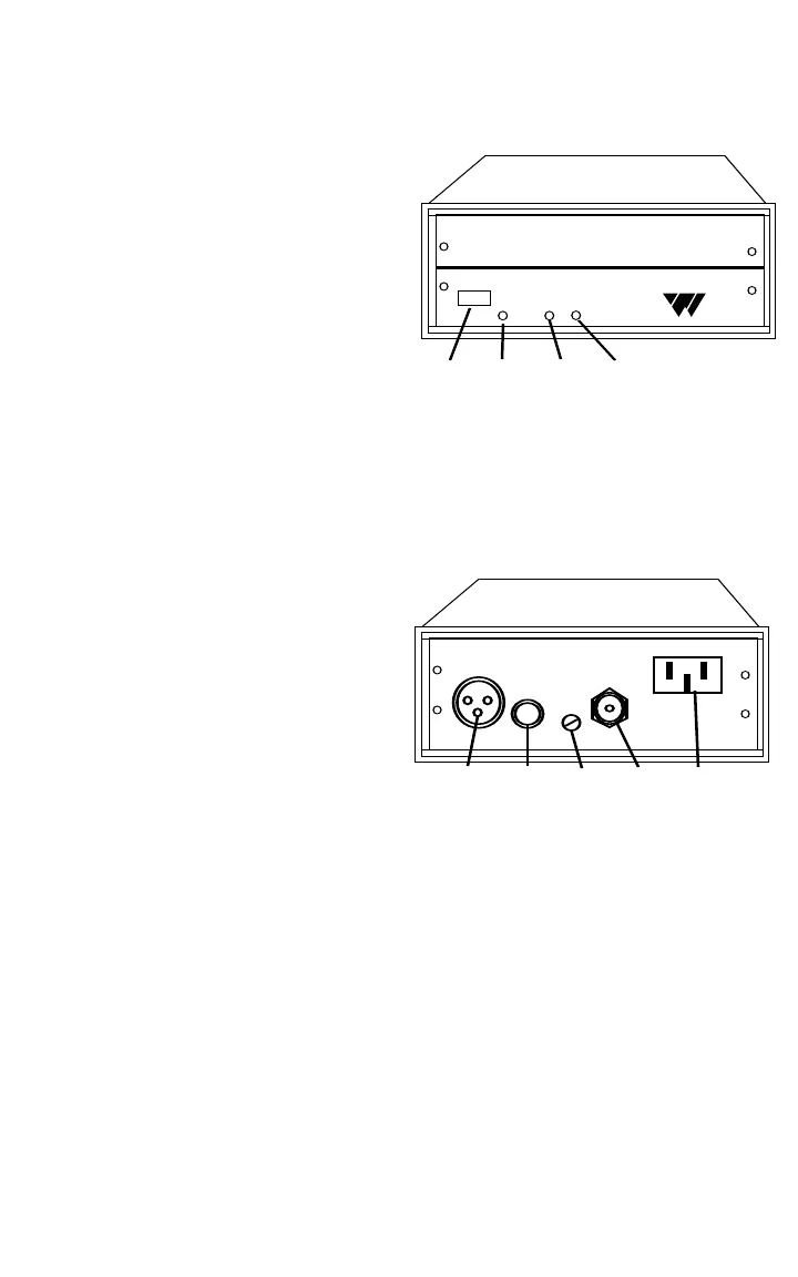
WMS R11, Front Panel:
(A) Power Switch - turns
Receiver on and off.
(B) Power ON Indicator - glows
when Receiver is on.
(C) RF Indicator - glows when
radio carrier is present.
(D) AF Indicator - flashes when
audio signal is present.
WMS R11, Rear Panel:
(A) Balanced Mic Output -
male XLR jack for use with
balanced Mic inputs on mixers
and amplifiers. Signal is on
pins 2 and 3, common is on
pin 1. Source impedance is
200 Ohms. Output is
0 - 160 mVrms. Any Load
impedance may be used.
(B) Unbalanced Line Output - 1/4" phone jack for use with unbalanced
Aux or Line inputs on mixers and amplifiers. The Line Output can also
accomodate balanced line-level inputs using a stereo 1/4" plug. The
signal is connected to the plug tip. The plug ring and sleeve are
connected to common. Source impedance is 100 Ohms. Output is
0 - 2 Vrms. Load impedance should be greater than 1000 Ohms.
(C) Output Level Control - provides adjustment of the Mic Output and
Line Output levels.
(D) Antenna Connector - 75 Ohm F-type connector for the system
antenna.
(E) Power Connector - the AC power cord plugs into the power
connector.
10
Power
RF AF
Williams
S
ound
Professional VHF Wireless Mic Receiver
Advanced Noise Reduction
Programmable Digital Tuning
AB CD
VHF Wireless Microphone Receiver
Model WMS R11
Balanced
Mic Output
Unbalanced
Line Output
Output Level Antenna
75 Ohm
Power
120 VAC
50/60 hz
3W
Williams Sound Corp.
Minneapolis, Minnesota, U.S.A.
ABCDE


