P/N: 4FT020-010
©2002 Vortech Engineering, LLC
All Rights Reserved, Intl. Copr. Secured
07FEB02 V2.0
(99-01SuperDuty(4FT V2.0))
3
H. Install the harmonic balancer puller. Evenly start
the three puller screws (M10 x 1.5). Engage the
forcing screw against the pivot and check align-
ment.
I. After ensuring the puller is properly aligned on
the face of the crank, slowly tighten the forcing
screw until the harmonic balancer has been
removed.
J. With a small amount of silicone on the keyway of
the new harmonic balancer, guide it on the
crankshaft and feel for alignment of the wood-
ruff key and the harmonic balancer keyway.
After the harmonic balancer has been aligned
on the crankshaft, use your harmonic balancer
installation tool to install the new harmonic bal-
ancer. Slowly tighten until the harmonic bal-
ancer is seated on the crankshaft.
2. HARMONIC BALANCER AND CRANK PULLEY INSTALLATION, cont’d.
NOTE: When using the harmonic balancer
puller, pay special attention to alignment
of the forcing screw and pivot. Improper
alignment can result in crankshaft dam-
age.
NOTE: The factory uses a small amount of sili-
cone to seal the crankshaft keyway.
Thoroughly clean the silicone and any
oil residue off of the crankshaft prior to
installing the Vortech harmonic bal-
ancer.
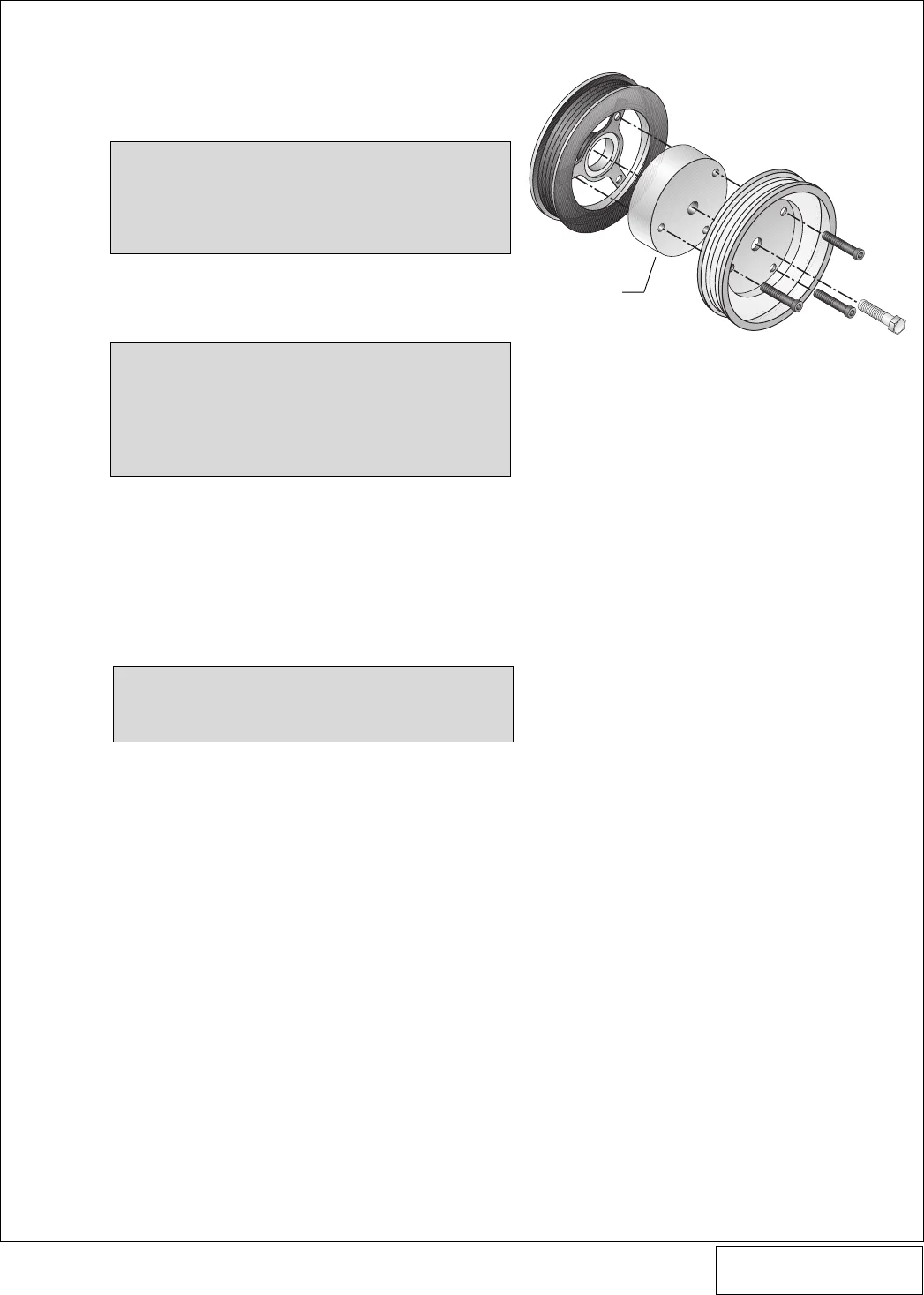
K. Remove the installation tool and place the su-
percharger drive pulley and spacer on the front
of the harmonic balancer. (See
Fig. 2-a
.) Feel-
ing for alignment, start the M12 x 1.5 x 65mm
center screw and rotate the supercharger drive
pulley until the three screw holes are aligned.
Start the three M10 x 1.5 x 40mm cap screws
with washers, evenly tighten all beginning with
the center screw. Torque the M12 screw to 80 ft/
lbs and the M10 screws to 25 ft/lbs.
L. Reinstall the rubber inspection plug (if previ-
ously removed) and the accessory drive belt.
Do not reinstall the fan and fan shroud at this
time.
NOTE: The use of Loctite blue is recommended
for all harmonic balancer and crank pul-
ley screws.
Fig. 2-a
SPACER


