CONVERGENCE ADJUSTMENT
CENTER CONVERGENCE ADJUSTMENT
1. Connect a crosshatch generator to antenna terminals.
2. Set Contrast control to low level to eliminate Blooming.
Reduce Brightness level to obtain black background if
necessary.
3. Adjust the angle between the four-pole magnet tabs 1 and 2
(Figure 2), and superimpose the red and blue vertical lines
in the center area of the picture screen. See Figure 4.
4. Keeping the tabs at the same angle, rotate them together to
superimpose the blue and red horizontal lines in the center
area of the picture screen. See Figure 4.
5. Adjust the six-pole magnet tabs 3 and 4 so the converged
red/blue line is superimposed on the green line. This is the
same procedure used in Steps 3 and 4. See Figure 5.
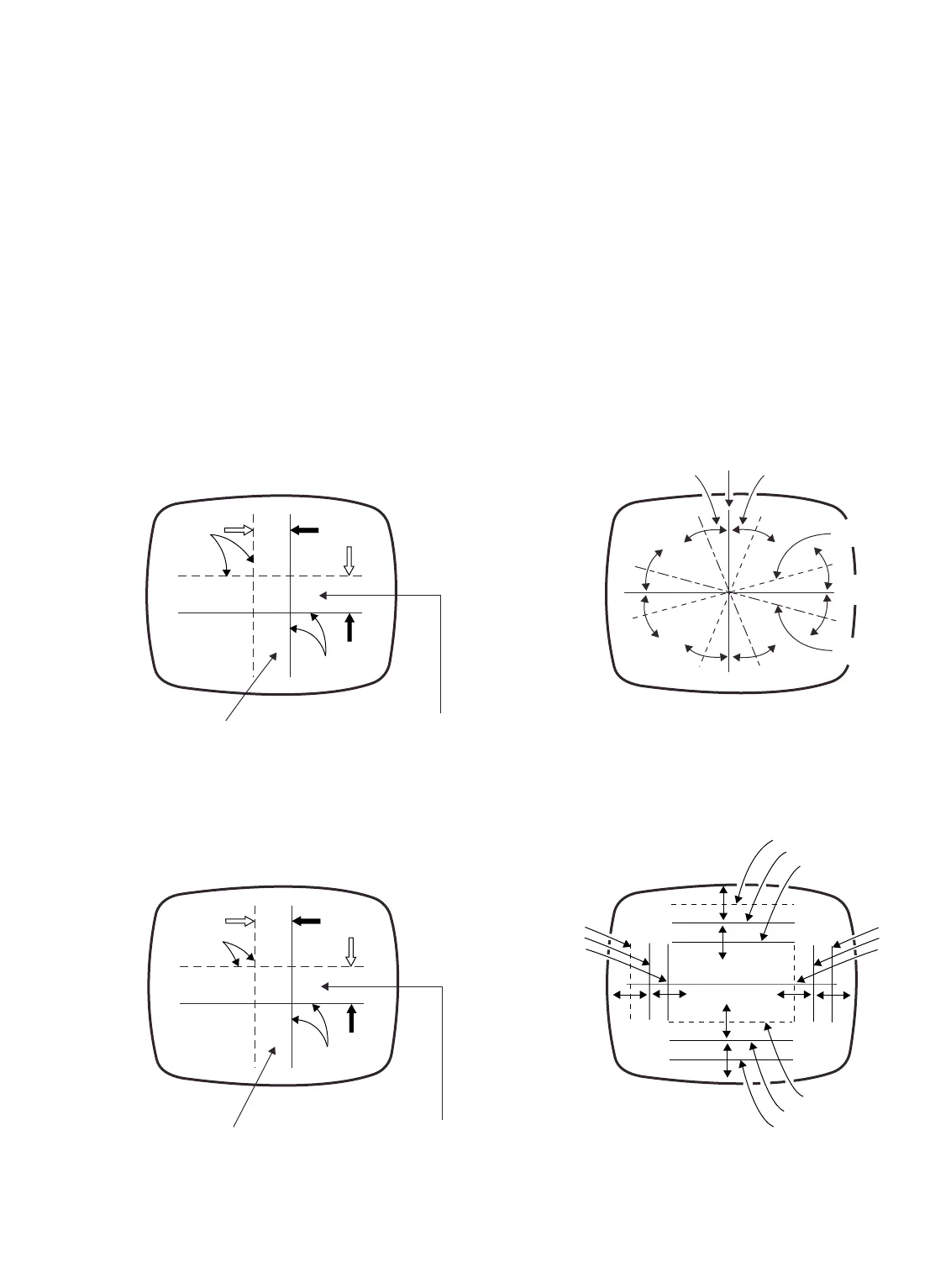
OUTER AREA CONVERGENCE ADJUSTMENT
The outer area convergence is performed by positioning of the
yoke as follows:
1. Move the top of the yoke toward or away from the picture
tube. This movement will affect the vertical lines at the top
and bottom and the horizontal lines at the sides.
See Figure 6.
2. Check that splits at 12 O’Clock and 6 O’Clock positions are
minimized, adjust yoke for best compromise. Secure with
wedge at 12 O’Clock position. See Figure 1.
3. Move the side of the yoke toward or away from the picture
tube to converge the horizontal lines at the top and bottom
and the vertical lines at the sides. See Figure 7.
4. Check that splits at 12 O’Clock and 6 O’Clock are
minimized, adjust yoke for best compromise. Secure yoke
position with the side wedges. See Figure 1.
Note: When reusing the rubber wedges, apply a small
amount of silicone rubber adhesive or hot melt to each
of the wedges.
— 11 —
top of yoke in and out.
line.
horizontal line.
side of yoke in and out.
green vertical line.
green horizontal line.