User’s Manual of GS-4210 Series
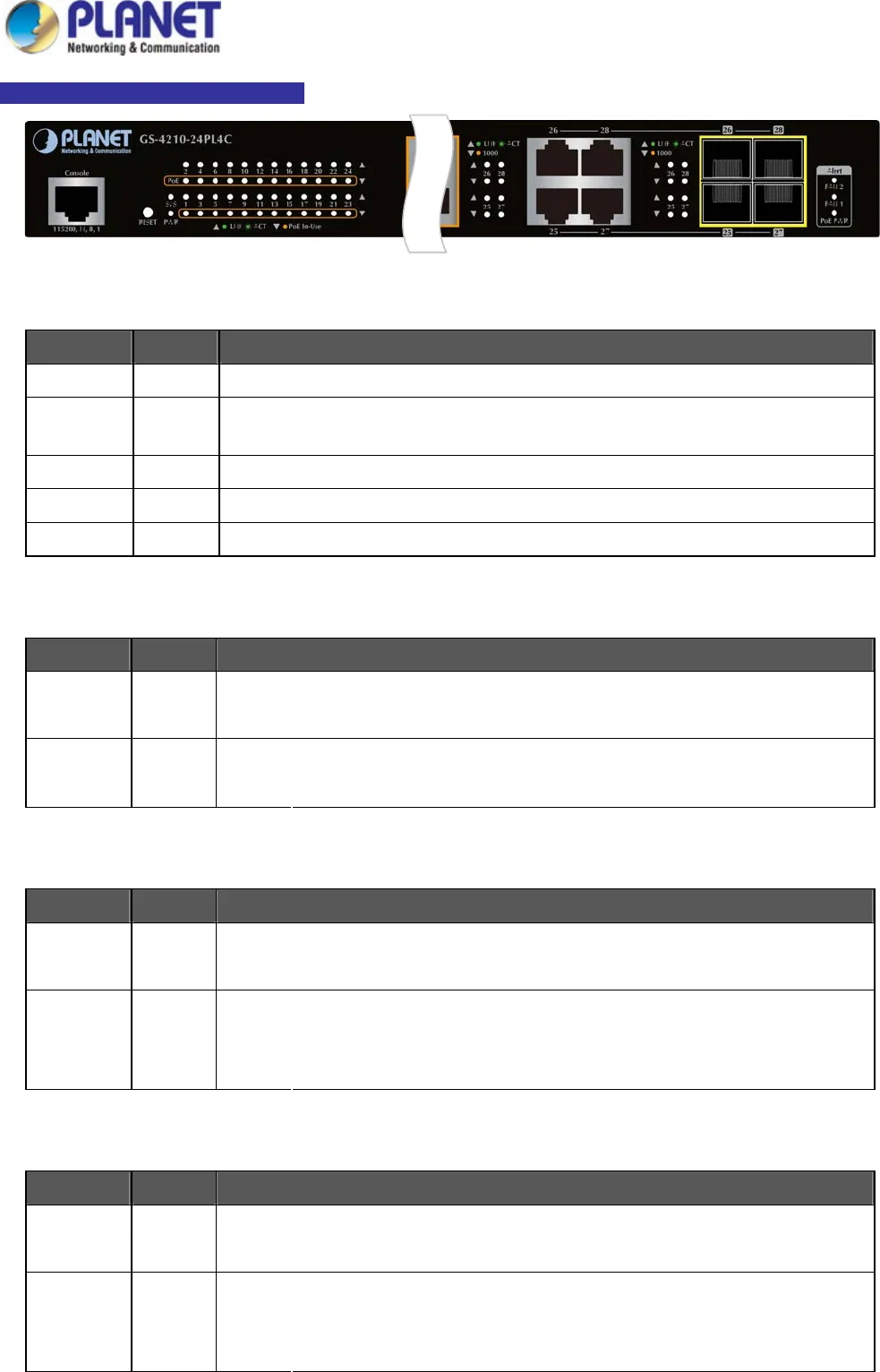
GS-4210-24P (L) 4C LED Indication
Figure 2-1-2c GS-4210-24P (L) 4C LED Panel
■ System / Alert
LED Color Function
PWR Green
Lights to indicate that the Switch has power.
SYS Green
Lights to indicate the system is working.
Off to indicate the system is booting.
FAN 1 Red
Lights to indicate that the FAN1 is down.
FAN 2 Red
Lights to indicate that the FAN2 is down.
PoE PWR Red
Lights to indicate that the PoE power is down.
■ 10/100/1000BASE-T interfaces (Port-1 to Port-24)
LED Color Function
Lights:
To indicate the link through that port is successfully established.
LNK/ACT Green
Blinks:
To indicate that the switch is actively sending or receiving data over that port.
Lights:
To indicate the port is providing 56V DC in-line power.
PoE Orange
Off:
To indicate the connected device is not a PoE Powered Device (PD)
■ 10/100/1000BASE-T interfaces (Port-25 to Port-28)
LED Color Function
Lights:
To indicate the link through that port is successfully established.
LNK/ACT Green
Blinks:
To indicate that the switch is actively sending or receiving data over that port.
Lights: To indicate that the port is operating at 1000Mbps.
1000 Orange
Off: If LNK/ACT LED is lit, it indicates that the port is operating at 10/100Mbps.
If LNK/ACT LED is off, it indicates that the port is link down.
■ 100/1000BASE-SX/LX SFP interfaces (Port-25 to Port-28)
LED Color Function
Lights:
To indicate the link through that port is successfully established.
LNK/ACT Green
Blinks:
To indicate that the switch is actively sending or receiving data over that port.
Lights: To indicate that the port is operating at 1000Mbps.
1000 Orange
Off: If LNK/ACT LED is lit, it indicates that the port is operating at 100Mbps.
If LNK/ACT LED is off, it indicates that the port is link down.
31


