User’s Manual of GS-4210 Series
2. INSTALLATION
This section describes the hardware features and installation of the Managed Switch on the desktop or rack mount. For easier
management and control of the Managed Switch, familiarize yourself with its display indicators and ports. Front panel
illustrations in this chapter display the unit LED indicators. Before connecting any network device to the Managed Switch, please
read this chapter completely.
2.1 Hardware Description
2.1.1 Switch Front Panel
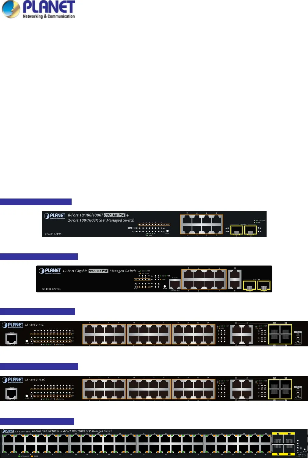
The front panel provides a simple interface monitoring of the Managed Switch. Figure 2-1-1a~ Figure 2-1-1d show the front
panel of the Managed Switch.
GS-4210-8P2S Front Panel
Figure 2-1-1a GS-4210-8P2S Front Panel
GS-4210-8P2T2S Front Panel
Figure 2-1-1b GS-4210-8P2T2S Front Panel
GS-4210-24P4C Front Panel
Figure 2-1-1c GS-4210-24P4C Front Panel
GS-4210-24PL4C Front Panel
Figure 2-1-1d GS-4210-24PL4C Front Panel
GS-4210-48T4S Front Panel
Figure 2-1-1e GS-4210-48T4S Front Panel
27


