Grayhill, Inc. • 561 Hillgrove Avenue • LaGrange, Illinois 60525-5997 • USA • Phone: 708-354-1040 • Fax: 708-354-2820 • www.grayhill.com
Standard Keypads
Keyboards and Keypads
ORIENTATION OF MODULES
A module, dependingon circuitry, may notbe
symmetrical. Rotating it 180° will result in a
different pin location. Please note the button
PRINTED CIRCUIT BOARD LAYOUT
Thislayoutprovidesthe horizontalprinted circuit boardlayout asviewed fromthetop sideof
thePCboard.Turningendtoendwillresultinadifferentpinlocation.However,thedimensional
relationshipwillremainthesame.
Lightable Modules–perdrawingbelow.
Thisdrawingindicatesthelayouttobeusedfora6buttonmodulewithlightsourcesmounted
twoways:thelampsfortheupper3buttonsaremountedfromthetoporcomponentsideofthe
board,andthelampsforthelower3buttonsaremountedbytheeasyreplacementmethod.(See
alsoLightSourceandLampMounting.)Lightsources,whenmountedfromthetopsideofthe
board,mustbemountedbeforethekeyboardmodules;whenmounted,lampshouldextendno
morethan.250"(6,35mm)abovetheboard.
Unlighted Module Lightable Module
C
L
C
L
C
L
.488–.003
(12,40–0,08)
TYP.
.687–.003
(17,45–0,08)
.687–.003
(17,45–0,08)
HOLETO
ACCOMMODATE
.032(0,81)DIA.
PIN
.045–.002
(1,14–0,05)
TYP.
(8PLACES)
.687–.003
(17,45–0,08)
.244(6,20)TYP.
.090
(2,29)
TYP.
.500–.003
(12,7–0,76)
.094
–.010
(2,39
–0,25)
identication, the pin location for the desired
circuitry, and the direction of mounting. It
is important to use this information when
designing a printed circuit board layout and
whencommunicatingwithGrayhill.SeeOrdering
Information–SpecialKeyboardModulesonthe
nextpage.
C
L
C
L
C
L
C
L
.687±.003
(17,45±0,08)
.687±.003
(17,45±0,08)
.270±.003
(6,86±0,08)
.112
±.003
(28,45
±0,08)
TYP.
HOLETO
ACCOMMODATE
.032(0,81)DIA.
PIN
.170(4,32)
RECOMMENDED
DIA.HOLE
ACCOMMODATES
LAMPINEASY
REPLACEMENT
MOUNTING
DIMENSIONSAREDEPENDENTON
LAMPSOURCE.APPROXIMATELY
.020(0,51)AND.100(2,54)APART
FORAT-1LAMPORLED
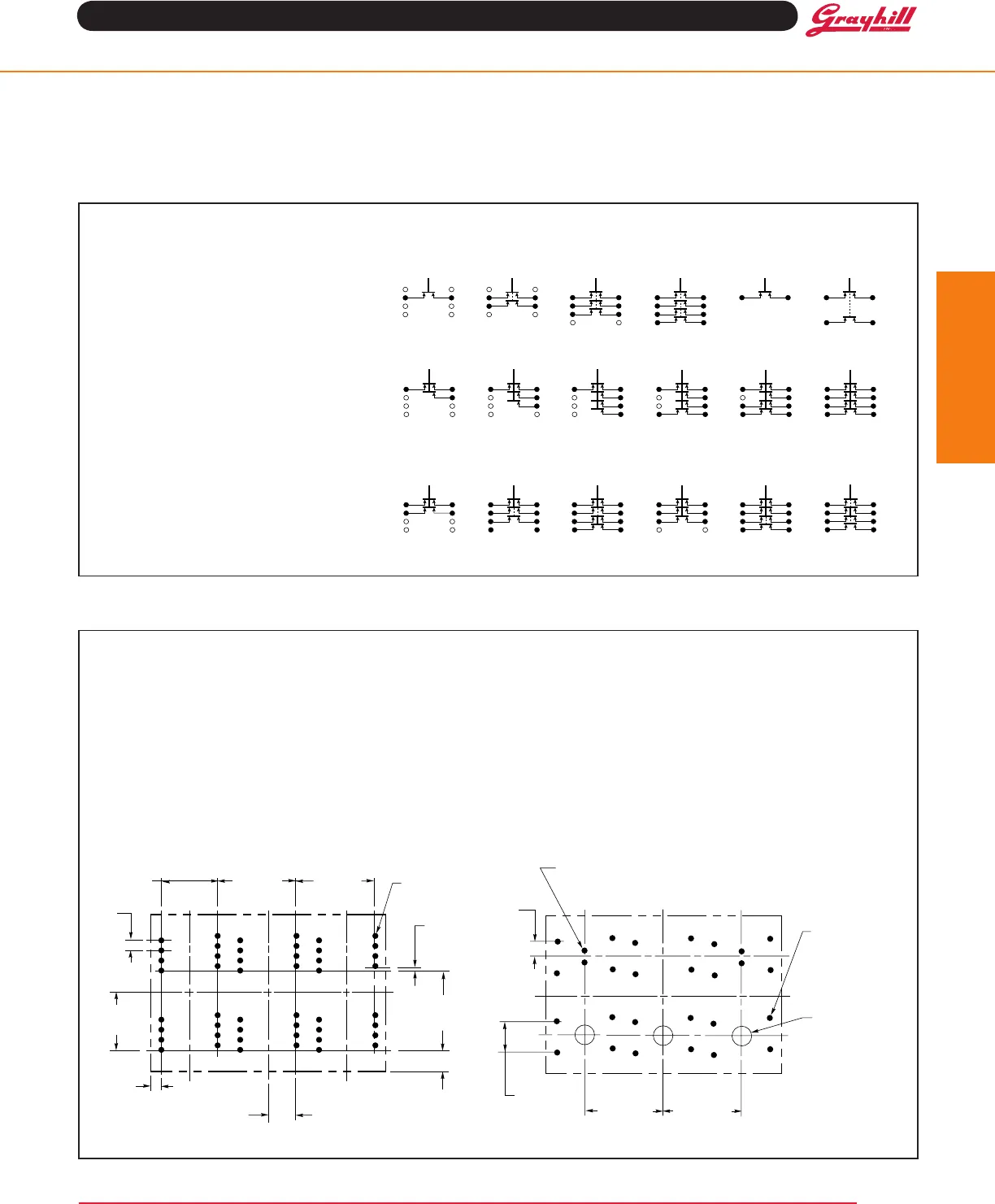
CIRCUIT DIAGRAMS
Thebottomviewofthelinedrawingsshows
number(A1,A2,etc.)nexttothepinlocations
of each switch section. These pin numbers
are directly related to the circuit diagrams.
Forexample,iftheswitchunderButtonAofa
standardmodulewereSPST,thepinswould
belocatedatthe"#2"Position.Ifthemodule
werealightableonewithSPSTcircuitry,the
pinswouldbelocatedatthe"#1"Position.If
otherlocationsaredesired,specifythem.
The coded circuits shown are suggested
possibilities and each button may carry a
differentcircuit.Locationofactivepinsoneach
buttonmaybevariedtoconformwithlayoutof
theprintedcircuitboard.Uptoa7-bitcodeis
possibleundereachbutton.
Combinations of simple circuitries are also
possibleasshowninthesamplediagrams.
Standard Modules Lightable Modules
Coded Circuitry–To 7 Bits/Button
Other Possible Circuit Configurations
22
3
2
3
2
1
2
3
4
1
2
3
4
1
2
3
4
1
2
3
4
1
1
1
4
1
4
C C C C C C
C C C
C
SPST
2PST 3PST
4PST
SPST 2PST
Note:Codedswitchesareconstructedsothatcommon(C)ismadeafterallothercontacts.


