Section 1 Basic Printer Functions 1-8
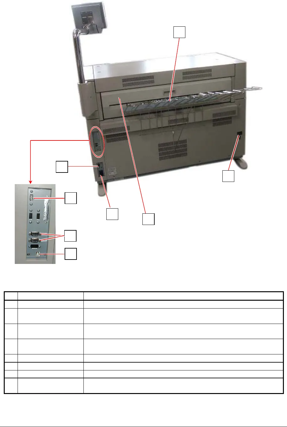
1. 5. 2 Rear view
Name of part Function
1 Tray Prints are stacked here after the ejection.
2 USB connector
(USB2.0)
Connect the cable to this terminal, which is included with the KIP
600 and KIP 2100. (max.5Vdc)
3 COM Port Connect the cable from the Optional Device.
(D-Sub Connector 9 pins: max.12Vdc (Small))
4 LAN Port Connect the LAN Cable to connect the KIP 7000 to the network.
(Do not connect a telephone line.)
5 Breaker It is possible to shut off supplying the AC power.
6 Inlet Socket Connect the Power Cord here.
7 Exit Cover Open the Exit Cover when you remove the mis-fed media.
8 Dehumidify Heater
Switch
Press “H” to turn on the Dehumidify Heater, and press “L” to turn it
off.
7
2
4
3
5
6
8
1


