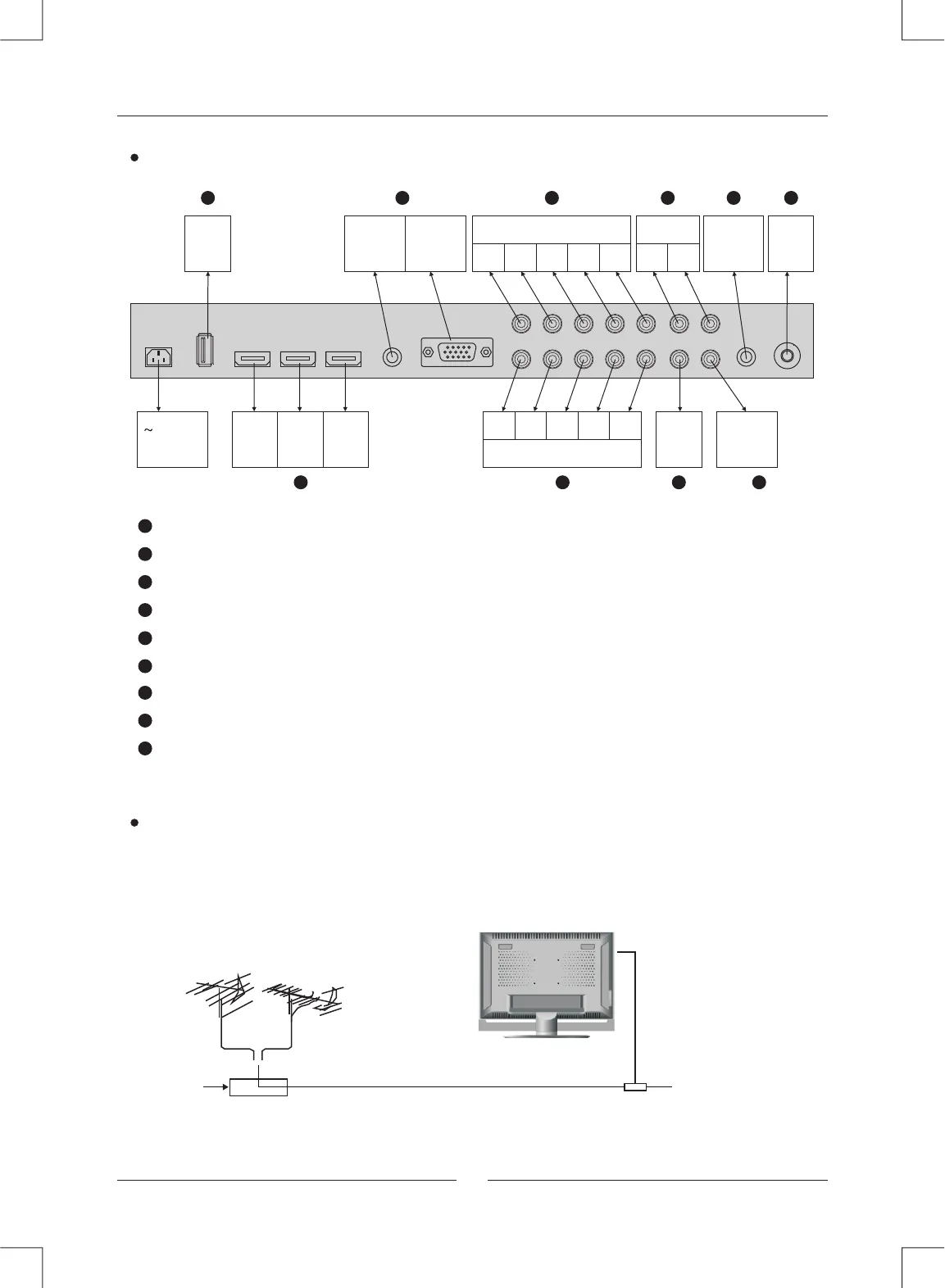
INPUT AND OUTPUT TERMINAL
COMPONENT & AUDIO IN 1
R L
PR/CR
PB/CB
Y
COMPONENT & AUDIO IN 2
R L
PR/CR
PB/CB
Y
IN IN IN
HDMI1 HDMI2 HDMI3
OUT
COAXIAL
IN
PC
IN
PC AUDIO
OUT
EARPHONE
IN
USB
IN
RF
IN
VIDEO
3
3
R L
AUDIO OUT
75 ohm Antenna Socket.
Video signal receivable. (AUDIO from YCBCR/YPBPR1)
YCBCR/YPBPR component signal receivable.
HDMI Input.
PC analog RGB signal receivable.
USB Input. (Only for service)
Coaxial signal (digital audio) output.
AUDIO output Terminal.
Earphone output Terminal.
5
5
6
7
8
9
6
7
8 9
3
1
1
2
2
4
4
110-240V
50/60Hz
Main Unit Descriptions
4
Connect antenna or video facility
1. Use 75Ω coaxial cable plug or 300-75Ω impedance converter to plug in antenna input
terminal on the side of the cabinet.
2. Connect the video facility to the audio, video in jack on the left side of the cabinet.
75 W Coaxial cable
VHF antenna
Mixer
UHF antenna
Input terminal of antenna
Coaxial antenna
plug to RF IN


