- 5 -
4- Control Panel Overview
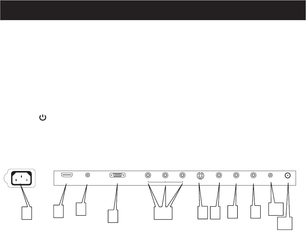
Connectors descriptions:
3
4
11
6
5
7
8
9
10
2
1
HDMI
PC IN
PC AUDIO IN
PBYPR
R F
S-VIDEO
L
VIDEO
R
Earphone
AC 120V~ 60Hz
1.
2.
3.
4.
5.
6.
7.
8,9.
10.
11.
Power receptacle AC120V 60Hz.
HDMI input interface.
PC audio input.
Dub15 PC interface.
Component input interface.
S-VIDEO input, connect video input from external device here.
Composite video input, connect video input from external device here.
L/R audio inputs (AV/S-VIDEO/ Component ) from exterior AV devices such as DVD players, Video Camera’s etc.
Earphone output.
Antenna input, connect antenna connector or aerial interface here to receive cable / aerial signal.
(1) Control Panel Functions:
1- TV/VIDEO To select the input signal: TV/VIDEO/S-VIDEO/Component/PC/HDMI
2- MENU Enter into MENU
3- CH+ TV channel up
4- CH- TV channel down
5- VOL+ Volume up / Right orientation
6- VOL- Volume down / Left orientation
7- POWER Power supply switch
Indicator Light Status
The indicator light is red when the TV is in standby mode. The indicator light is green when you press
the ' ' key
(2) Illustration of Connectors
Component


