P
P
4
4
V
V
T
T
G
G
-
-
M
M
11
Power Source Selection for USB: JUSBV2
USBV2 Assignment Description
13
Pin 1-2 close
+5V
+5V f or USB at the JUSB 3~4
connector ports.
13
Pin 2-3 close
+5V standby
Voltage
JUSB3~4 ports powered with
standby voltage of 5V
Front USB Header: JUSB3~4
This header allows user to connect additional USB cable on the PC
front panel, and also can be connected with internal USB devices,
like USB card reader.
Pin Assignment Pin Assignment
1 +5V (f used) 2 +5V (f used)
3 USB- 4 USB-
5 USB+ 6 USB+
7 Ground 8 Ground
2
1
10
9
JUSB3/4
9 Key 10 NC
Case Open Connector: JCI1
This connector allows system to monitor PC case open status. If
the signal has been triggered, it will record to the CMOS and show
the message on next boot-up.
Pin Assignment
1 Case open signal
12
JCI1
2 Ground
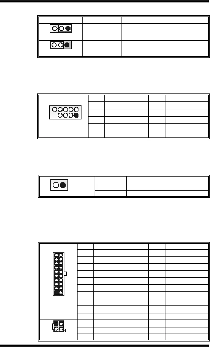
Power Connectors: JATXPWR1/JATXPWR2
JATXPWR1: This connector allows user to connect 20-pin power
connector on the ATX power supply.
JATXPWR2: By connecting this connector, it will provide +12V to
CPU power circuit.
Pin Assignment Pin Assignment
1 +3.3V 11 +3.3V
2 +3.3V 12 -12V
3 Ground 13 Ground
4 +5V 14 PS_ON
5 Ground 15 Ground
6 +5V 16 Ground
7 Ground 17 Ground
8 PW_OK 18 -5V
9 Standby Voltage +5V 19 +5V
20
11
10
1
JATXPWR1
10 +12V 20 +5V
Pin Assignment Pin Assignment
1 +12V 3 Ground
1
2
3
JATXPWR2
2 +12v 4 Ground


